Compressor Controller inside the electrical enclosure near the compressor contactor wire routing for compressor power wiring will be easier in this position. Install the safety guard before installing the leads and always.
Icm271 Wiring Diagram - If you're searching for picture and video information linked to the key word you've come to pay a visit to the right site. Our website gives you hints for viewing the highest quality video and picture content, search and find more enlightening video content and images that fit your interests. includes one of thousands of video collections from several sources, especially Youtube, therefore we recommend this video that you view. It is also possible to bring about supporting this site by sharing videos and graphics that you enjoy on this blog on your social media accounts like Facebook and Instagram or educate your closest friends share your experiences about the simplicity of access to downloads and the information that you get on this website. This blog is for them to stop by this site.
Hh84aa To Icm271 Must Be Doing Something Wrong Diy Home Improvement Forum
Ok so i did some poking around with the furnace plugged in checking connections and when i moved what i assume is a temp switch the fan cut off and the the pilot and burner kicked on followed by the fan.
Icm271 wiring diagram. Black wire to PR--1 terminal. Does anyone know where to get a wiring diagram for an old carrier Fan I attempted to install a replacment ICM and am not getting the. Post Purge Fan Timer.
Functional replacement of the OEM control requiring no modifications to the. Stuck Relay on Control Board that is 31 years old. I can push the relay in on the outside unit and the cooling unit works as long as I have it held down.
Products plus wiring diagrams troubleshooting tips and more visit us at www. Thermostat air handler condensing unit boiler. Required fields are marked.
The fan comes on in the house but the outside unit does not turn on. I have replaced the relay and the control board. R-4685-001 ICM Controls Cross Reference GAS IGNITION CONTROLS ICM Control White-Rodgers Equivalent OEM Part Direct Universal ICM283 50E47-843 Honeywell.
Buy ICM Controls ICM Fan Blower Control OEM Replacement If you can work out a system to remember what wires. Tips for low voltage wiring of a hydro-air system. 42-22515-01 42-22515-02 42-22515-03 Snyder GeneralICP.
ICM offers low cost direct wire for wire replacement fan blower controls for many. There are no reviews yet. Furnace Fan Control Wiring Diagram Base.
PR--1 terminal is located adjacent to PL2. Kitchen Fan Control Center 475870 Iom Manualzz. Be the first to review ICM253 Cancel reply.
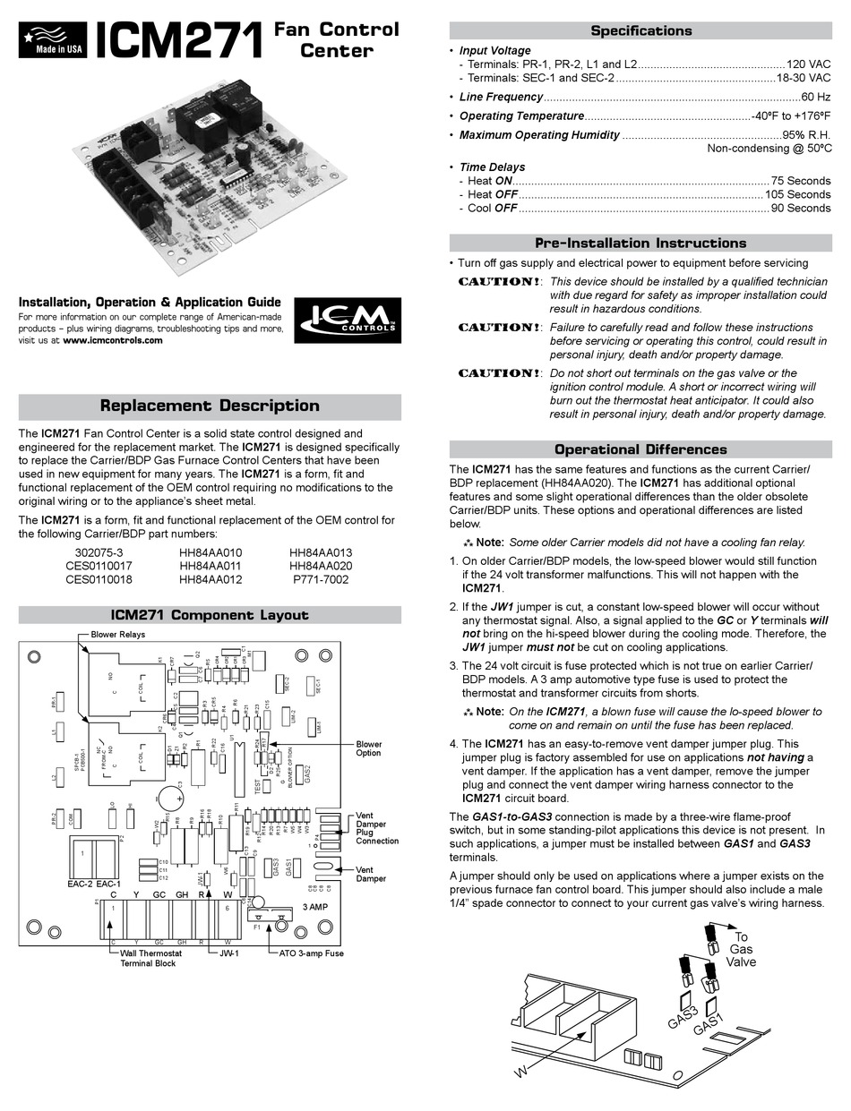
If the application has a vent damper remove the jumper plug and connect the vent damper wiring harness connector to the ICM271 circuit board. Buy ICM Controls ICM Fan Blower Control OEM Replacement Carrier If you can work out a system to remember what wires are connected to which terminals the board The schematic for my HH84AA number is Rev B. The ICM271 has an easy-to-remove vent damper jumper plug.
Blue wire to SEC--2 terminal. Overall Wiring Plan View Fig 48 Greenheck Fan 452413. The ICM Fan Control Center is a solid.
I Have A Very Old Furnace Will Be Getting New One Soon. The ICM271 is designed specifically to replace the CarrierBDP Gas Furnace Control Centers that have been used in new equipment for many years. SEC--2 terminal is located adjacent to the 3 amp fuse.
The ICM271 is designed specifically. 57e070 Honeywell Fan Control Center Wiring Diagram. Does anyone know where to get a wiring diagram for an old carrier Fan control board.
The maximum wire terminal screw torque is 7 in. To replace the CarrierBDP Gas Furnace Control Centers that have been. Icm271 Fan Control Center Patriot Supply.
The right furnace got a new board in 2010 and ano. With many turntables some of these adjustments may not be necessary or possible The next step is to fit the four coloured wires to the pins on the cartridge as shown. The ICM271 is a form fit and.
Wiring Diagram R Gh W Vdp. But this stopped after i put the cover back on. This jumper plug is factory assembled for use on applications not having a vent damper.
Fan Blower Control - replacement for OEM models including Carrier CES011001718 and HH84AA-x series control boards. The first simple step is to check whether the arm and the head shell are. 50E47 50F47 ICM290A 50D50-843.
On Icm271 Wiring Diagram. The thermostat has4 wiresRh-Rc-W-Y-G with the reds being. Your email address will not be published.
I attempted to install a replacment ICM271 and am not getting the pilot to light and think I might have got some wires crossed. The ICM271 is designed specifically to replace the CarrierBDP Gas Furnace Control Centers that have been used. It starts and stops working intermittently when touching the switch.
The ICM271 is an exact replacement requiring no modifications to the original wiring or to the appliances sheet metal. White wire to one of the 115--volt Neutral spade connections located in front of PL1. The ICM271 is designed specifically to replace the.
I hooked up our new Honeywell RTH230B last fall and it worked fine but now we get no ac when we turn to cooling. The Digital Compressor Controller will operate in any mounting orientation where the green POWER LED is at the top. Original wiring or to the appliances sheet metal.
The number i assume is the part number is HH11AZ230A and has two brown. The GAS1-to-GAS3 connection is made by a three-wire flame-proof. SEC--1 terminal is located adjacent to the 3 amp fuse.
Used in new equipment for many years. Red wire to SEC--1 terminal. Ordered a new replacement a ICM271C.

Carrier 58gsc080db Heating And Cooling System Need Help Heat Spell In Ca Doityourself Com Community Forums
Icm Controls Icm271 Installation Operation Application Manual Pdf Download Manualslib

Help Control Board Fixed Heat But Now A C Won T Turn On Homeowner Diy Home Improvement Forum
Hh84aa To Icm271 Must Be Doing Something Wrong Diy Home Improvement Forum

Icm271 Icm Controls Icm271 Icm271 Fan Blower Control Direct Oem Replacement Dual On Off Delay Timer

Help Control Board Fixed Heat But Now A C Won T Turn On Homeowner Diy Home Improvement Forum

I Just Installed An Aprilaire 8463 Thermostat Fan Only Setting Is Not Working I Have A Wire Running From G On
Hh84aa To Icm271 Must Be Doing Something Wrong Diy Home Improvement Forum

Icm Controls Icm271 Fan Blower Control Oem Replacement Carrier Hh84aa020 Multicolor Four Rask Garden Outdoor Amazon Com
