Starter Replacement Gm 3800 Series 2 Gm 3 8l Engine Diagram Wiring Diagram Update 97 Pontiac Evap Diagram Wiring Diagram Data 1994 Camero 3 4 Liter Gm Engine Diagram 3800 Series 2 Engine 2000 Buick Regal Engine Diagram Diagram Data 3800 V6 Engine Diagram Wiring Diagram Meta Gm 3800 Series Ii Engine Servicing Repairs 2002 Firebird Engine Diagram Wiring Diagram Gm 3800 Series Ii Engine Servicing Repairs 9a3d6 2002 Pontiac 3800 Series 2 Engine Diagram Wiring. Computer wiring diagram in a 1997 buick lesabre how to replace ignition control module icm in a 1997 buick lesabre by the gentleman farmer captianwiggles 3 years ago 8 minutes 20 seconds 69 961 views how to replace the icm or ignition control module in a 1997 buick lesabre gm v6 3800 series ii rough idle hesitation on.
3800 Ignition Control Module Wiring Diagram - If you're looking for picture and video information linked to the keyword you've come to visit the right site. Our site gives you suggestions for seeing the maximum quality video and picture content, hunt and find more informative video content and graphics that match your interests. comprises one of thousands of video collections from several sources, particularly Youtube, so we recommend this movie that you view. This site is for them to visit this site.
89 Buick Park Avenue Ignition Coil To Ignition Module Wiring Diagram
Need wiring diagram for 1988 buick 30 v6 ignition control module - Answered by a verified Buick Mechanic We use cookies to give you the best possible experience on our website.
3800 ignition control module wiring diagram. 7 Pin Ignition Module Wiring Diagram wiring diagram is a simplified satisfactory pictorial representation of an electrical circuit. Once the ICM gets power it in turn supplies power to. Ohm Wiring Diagram July 6 2019.
What tools do i need for the ignition module test. It consists of guidelines and diagrams for various kinds of wiring strategies and other items like lights windows etc. Ford Ignition Control Module Wiring Diagram ford 302 ignition control module wiring diagram ford ignition control module wiring diagram Every electric arrangement consists of various different pieces.
Making Sure The Crank Sensor Is Getting Power. By continuing to use this site you consent to the use of cookies on your device as described in our cookie policy unless you have disabled them. If not the structure wont function as it ought to be.
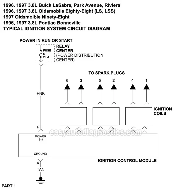
Ignition System Circuit Diagram 1996 1997 3 8l Buick Oldsmobile Pontiac. When you turn the Key to start the engine the ignition control module gets power 12 Volts and Ground. The pulsing means the wire from the computer to the ignition control module is good and the computer is working.
All old ford truck owners need to know ignition control module from new and old duration. Image Info File Name. As the engine cranks the ignition module receives the crank sensor signal.
Use a wiring diagram for the year model of your vehicle. The cam sensor if equipped. Leave a Reply Cancel reply.
3800 Series 2 Beyond Ignition Module Issue. This tells you that the module does have a good path to Ground. Gm 3800 Ignition Wiring Diagram Meta Snow Producer Scuderiatorvergata It.
Ford Ignition Control Module Wiring Diagram Effectively read a electrical wiring diagram one offers to know how the components within the system operate. Gm Ignition Module Wiring Diagram wiring diagram is a simplified satisfactory pictorial representation of an electrical circuit. For this test go to.
It shows the components of the circuit as simplified shapes and the capacity and signal connections amongst the devices. Wiring Diagram includes several in depth illustrations that display the connection of varied items. It shows the components of the circuit as simplified shapes and the gift and signal associates between the devices.
Accel Control Module Wiring Diagram Wiring Diagram Library Ford Ignition Control Module Wiring Diagram. Gm 3800 Wiring Diagram Export Platform Congressosifo2018 It. 3800 Series 2 Firing Order.
This wiring diagram is for the 1980 and later four pin ignition module. Wiring Diagram consists of numerous detailed illustrations that display the relationship of varied items. It contains directions and diagrams for different types of wiring methods as well as other things like lights windows etc.
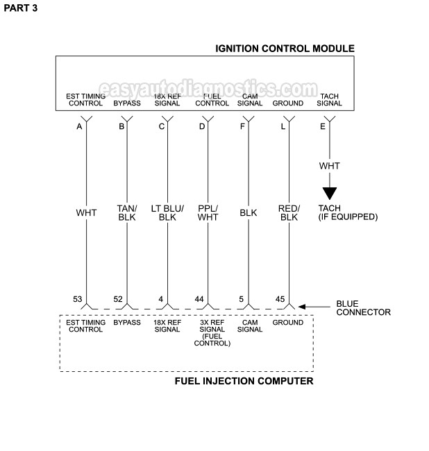
Each component ought to be set and connected with different parts in specific way. February 6th 2019. Part 3 Gm 8l Ignition Control Module And Crank 3x 18x Sensor Test.
2003 3800 Series 2 OBD2 PCM wiring instructions for L36L67 Fiero swaps using 2003-newer 4T65-E transmissions only Pin Wire Color Circuit Description Action Pin Additional Info 3 orn fuel level output control circuit delete 4 lt grn shift solenoid A control 1-2 shift sol connect to. For example if a module is usually powered up and it also sends out the signal of half the voltage and the technician would not know this hed think he provides a challenge as he would expect a new 12V signal. Pontiac Trans Sport Wiring Diagram Wiring Schematic Diagram 89 Repair Guides 1996 1997 Buick Regal Pontiac Grand Prix 3800 Engine Wiring Part 1 Gm 3 8l Ignition Control Module And Crank 3x 18x Sensor Diagram Diagram Of 1997 Series 2 3800 Engine Full Version Hd 3800.
Mastertech marine chrysler force outboard wiring diagrams size. Set multimeter to read resistance ohms verify distributor pick up sensor resistnace is between 350 to 550. The 3 ignition coil packs sitting on top of it.
Lt1 Ignition Control Module Wiring Diagram Wiring Library Ford Ignition Control Module Wiring Diagram. 1998-2002 3800 Series 2 OBD2 PCM wiring instructions for L36L67 Fiero swaps Pin Wire Color Circuit Description Action Pin Additional Info 3 orn fuel level output control circuit delete 4 lt grn shift solenoid A control 1-2 shift sol connect to A of4T65-E tra n sm ic eud 5 dk blu high speed fan control connect to h ig sp edfanrlyu. Rule A Matic Float Switch Wiring Diagram July 6 2019.
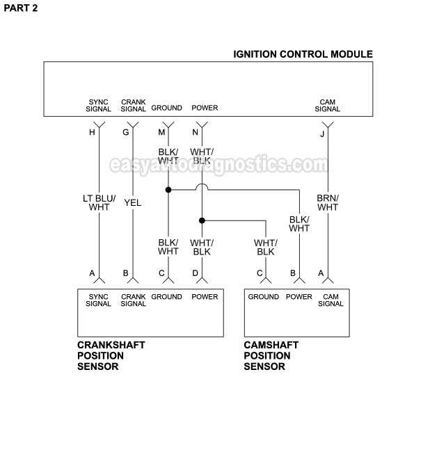
The next step is to make sure that the ignition module is feeding the crankshaft position sensor with power. Your email address will not be published. Your multimeter registered 12 Volts.
I Need A Wire Diagram Of Icm Crank Cam Sensor For Olds 1995 3 8l Regency 98
Ignition System Circuit Diagram 1996 1997 3 8l Buick Oldsmobile Pontiac
Part 3 Gm 3 8l Ignition Control Module And Crank 3x 18x Sensor Test
Icm Test Gm Forum Buick Cadillac Olds Gmc Pontiac Chat
Part 2 Testing The Ignition Module And Crank Sensor Gm 3 1l 3 4l
Ignition System Circuit Diagram 1996 1997 3 8l Buick Oldsmobile Pontiac
Ignition System Circuit Diagram 1996 1997 3 8l Buick Oldsmobile Pontiac
I Have A 1995 Buick Regal Custom 3800 V6 With About 100 000 Miles Car Wont Start Replaced Battery Ignition Coil
Gm 3 8l Vin 3 3800 Vin C Engines Code 41 Diagnosis Auto Service World


