See also Erratic Shutdown Improperly adjusted DNFT. M9M9D M11M11D Attention This document contains wiring and flow diagrams for the models listed in the table below.
Dnft No Flow Wiring Diagram - If you're looking for video and picture information linked to the key word you've come to visit the right site. Our site gives you suggestions for viewing the highest quality video and image content, hunt and locate more informative video content and graphics that fit your interests. includes one of tens of thousands of movie collections from several sources, especially Youtube, therefore we recommend this video for you to view. You can also bring about supporting this website by sharing videos and images that you like on this site on your social media accounts such as Facebook and Instagram or educate your closest friends share your experiences about the ease of access to downloads and the information that you get on this website. This site is for them to visit this site.

No Flow Dnft 2 Min Valve Electrical Connector
They can be accommodating when determining a fault in the connections installing new wires and devices locating electrical outlets etc.

Dnft no flow wiring diagram. Just what is a Wiring Diagram. Additional wiring information is available in er 5607 including how to properly ground your dnft a potential source for dnft headaches that is easily prevented. Normally closed contacts become open.
A wiring diagram is a straightforward visual representation of the physical connections and physical design of an electrical system or circuit. Either pump clean oil through lubrication system with a purge pump or run the compressor to cycle the divider valve. Three or Four Button Switch Panel Wiring Diagram.
Select Electrical Engineering and Basic Electrical. Stand Alone Purge System. Wiring Diagrams are created to be easy to know and easy to construct.
M9 -020 -021 -022 Old-style Wiring Diagram. It demonstrates how the electric wires are interconnected and can likewise show where fixtures and components could be connected to the system. It is majorly used by building planners architects and electricians to present the wiring connections in a building a room or even a simple device.
As stated previous the traces at a Maf Wiring Diagram signifies wires. Describe the meaning of the G-W in diagram component R. I also show you how you can figure out the wires without a wiring diagram.
I installed last version of SVGView but still have the problem and i uninstalled and re install but the still the same issue i did not got any errors while installing and did not have any errors when running. Do not over tighten. This really is useful for each the individuals and for experts that are looking to learn more on how to set up a functioning surroundings.
Fuel Pressure Safety Switch. Wet Powersports Wiring Diagram. Dry Powersports Wiring Diagram.
Transporter Current Flow Diagram No. Model Numbers Fill Vent Solenoid Refer to. Identify the desired model then click on the blue text to view the desired diagram.
When and How you can Use a Wiring Diagram. Large Rocker Style Switch Panel Wiring Diagram. Describe and identify the diagram component U.
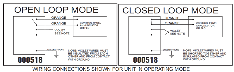
2 - Rear window wiperwasher relay 174 4 - X contact relief relay 18 8 - Automatic intermittent washwipe relay 99 11 - Dual tone horn relay 53. Wiring diagrams that accompany ariel dnfts present a visual representation of how to successfully connect your digital no flow timer. Describe the meaning of the C13 in the diagram component Q.
Here are optional customer solutions. Injunction of two wires is usually indicated by black dot at the junction of 2 lines. Wiring Diagram contains the two illustrations and step-by-step directions that might allow you to actually construct your undertaking.
Describe the meaning of the SD in diagram component T. Elsawin NO Wiring Diagrams. Here is a video on how you can test your MAF Sensor using a basic 5 Multimeter.
Flow Switches Speed Plugging FF R F R Anti-Plug. - Positive connection 54 in tail light wiring harness - Only models with no startstop system 2 - Only models with startstop system 3 - see applicable current flow diagram for headlights 4 - see applicable current flow diagram for engine 5 - Only models with no electric interface WI-XML Стр. Describe the meaning of the 2 in diagram component S.
Wiring Flow Diagrams. The contacts shown in the Relay Contact diagram shows 2 different type relays. Wiring diagrams are mainly used when trying to show the connection system in a circuit.
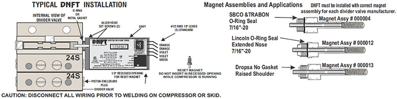
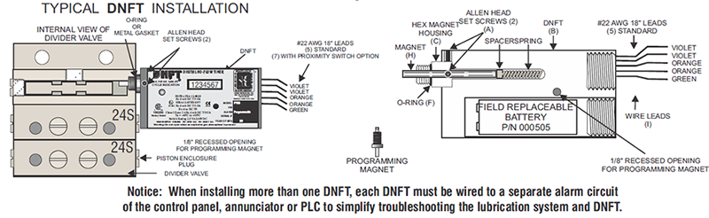
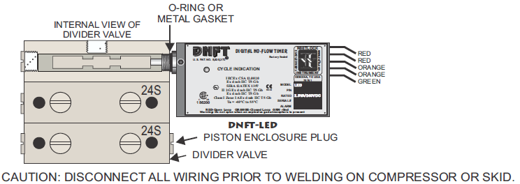
Loosen set screws slide DNFT all the way onto hex of magnet housing and torque to 25 lbs x inch 28 Nm max. Switch Panel Wiring Diagrams. As the creation of wiring diagram is an electrical concept you need to select Electrical Engineering from the side panel.
But it does not imply link between the wires. Occasionally the cables will cross. Therell be principal lines.
79 1 Edition 052003 For alternatives to relay and fuse locations as well as assignment of multi-pin connector wiring see Fitting locations section. Wiring Diagram Book A1 15 B1 B2 16 18 B3 A2 B1 B3 15 Supply voltage 16 18 L M H 2 Levels B2 L1 F U 1 460 V F U 2 L2 L3 GND H1 H3 H2 H4 F U 3 X1A F U 4 F U 5 X2A R Power On Optional X1 X2115 V 230 V H1 H3 H2 H4 Optional Connection Electrostatically Shielded Transformer F U 6 OFF ON. Force Feed Lubrication System No-Flow Devices 24 Hour Support North America.
UNDERSTANDING TOYOTA WIRING DIAGRAMS WORKSHEET 1 1. LED does not blink and control panel indicates lube no-flow. The left is a 2-pole relay and the right is a 3-pole relay.
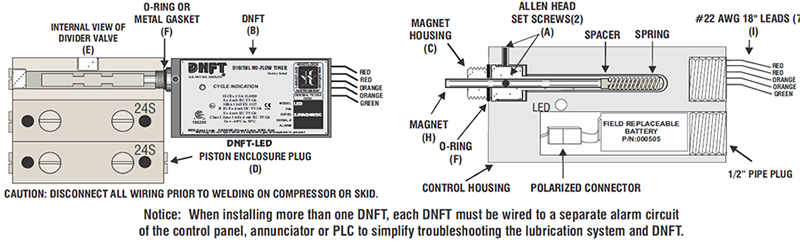
Normally open contacts become closed and the NC. When the relay coil is energized the contacts change state. 1 740-397-3602 Advanced Application Compressors with DNFTs can either use the no-flow switch to directly shutdown the unit or use the included proximity switch with the package control panel to create customized control logic.
M9 M11 old-style solenoids. Elsawin can not see wiring diagram pictures. This differs a schematic representation where the plan of the parts affiliations on the diagram usually does not represent the elements physical areas in the finished tool.
For this you need to use valid email id and a password. Fuel Pressure Safety Switch Wiring Diagram. A wiring diagram generally provides details about the relative setting and also setup of devices and terminals on the tools to help in building or servicing the gadget.
Dnft Led P N 000506 Dnft Prg P N 000518 Digital No Flow Timer Dnft Digital No Flow Timer For Compressor Lube Systems Whitlock Instrument Dnft Whitlock Noflo Whitlock Instrument Dnft 000518
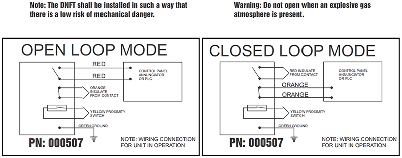
Dnft Led P N 000507 P N 000507 Dnft Led Ps Digital No Flow Timer With Dedicated Proximity Switch Install On Dropsa Lincoln Sbco Lubriquip Divider Block Switch Rating 2 5va 240vdc Dnft Led P N 000506 Dnft Prg P N 000518 Digital No Flow
Dnft Prg P N 000518 Digital No Flow Timer Dnft Digital No Flow Timer For Compressor Lube Systems Whitlock Instrument Dnft Whitlock Noflo Whitlock Instrument Dnft 000518 Prg Timer Model Number
Ariel Corporation Arielcorp Com
Dnft Prg P N 000518 Digital No Flow Timer Dnft Digital No Flow Timer For Compressor Lube Systems Whitlock Instrument Dnft Whitlock Noflo Whitlock Instrument Dnft 000518 Prg Timer Model Number
Dnft Prg P N 000518 Digital No Flow Timer Dnft Digital No Flow Timer For Compressor Lube Systems Whitlock Instrument Dnft Whitlock Noflo Whitlock Instrument Dnft 000518 Prg Timer Model Number

Dnft
Dnft Led P N 000506 Dnft Prg P N 000518 Digital No Flow Timer Dnft Digital No Flow Timer For Compressor Lube Systems Whitlock Instrument Dnft Whitlock Noflo Whitlock Instrument Dnft 000518

Ariel Corporation Arielcorp Com
