Barrier is an ideal solution for managing access points in residential and industrial areas when traffic volumes are medium and high. Connect all electrical wiring exactly as directed in the Connection Diagram.
Boom Barrier Wiring Diagram - If you're searching for video and picture information related to the key word you've come to pay a visit to the ideal blog. Our site gives you suggestions for seeing the maximum quality video and image content, hunt and find more informative video articles and images that fit your interests. includes one of thousands of movie collections from several sources, particularly Youtube, therefore we recommend this video for you to view. This site is for them to visit this site.

Essl Boom Barrier Connection Diagram Youtube
Engineering Specifications NAM-BL52-ES-EN-A 38g Specifi BL52 Extra-long Barrier 104 SUBMITTALS A.

Boom barrier wiring diagram. The setup uses again four ports for boom barrier servos 2 primary and 2 secondary booms and four ports for the level crossing lights. Wait for the complete setting of the concrete. Preparation instructions and recommendations.
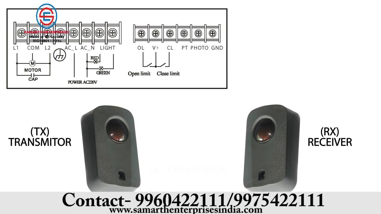
Nice barriers are designed to professionally control every type of access. Storage and handling requirements and recommendations. The input has RC hardware filter and 10 ms software filter the width of pulse required to be over 100 ms 1 fall to 0 trig to protect from crash to obstructer and 0 to 1 trig barrier boom to move up.
Remoter 4 pcsM16 X 120mm expansion bolt used to fix barrier housing onto foundation. If more lights are attached can can evenly connect them in parallel to the existing ones. Boom arm with rubber 2 pcs.
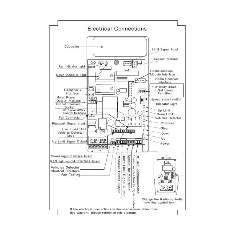
Please refer to drawing below. Infrared Photocell input Either active or passive input 005V or short as logic 0 3V24V or open as logic 1. Magnetic Toll-RC01001 Barrier Opener w 10ft Round Boom Orange MHTM Manual Magnetic Toll Brochure Wiring Diagram.
Wiring Diagram MattzoLevelCrossingController with PCA9685 Autonomous Mode. It suits for passage clearances of up to 6 m. Magnetic Toll-RCS1001 Barrier Opener w 10ft Octagonal Boom Orange MHTM Manual Magnetic Toll Brochure Wiring Diagram.
In the graph shown in Figure 2 from the value obtained from this point trace a horizontal line until it intersects the line of the manoeuvre cycles. Attach the boom arm to the flange using the boom attachment kit in accessory box. Unscrew the 4 nuts that hold the base joined to the anchoring brackets and position the rack on the plate Fig.
Up Down input. Magnetic Toll-RCS1201 Barrier Opener w 12ft Octagonal Boom Orange. Equipment description dimensions electrical wiring diagrams for installation and manufacturers technical manuals on each product to be used including.
Secure the boom flange in accessory box to the drive shaft using the using two M10 mm x 25mm hexagon socket screws. Any activity in the entrance and exit lanes should be monitored to ensure a safe operation when opening or closing the barrier gates or to prevent altering or vandalism. Never move the barrier rod for any reason until it horizontal and do not perform the emergency or manual ma-.
130 WIRING DIAGRAMS 140 SPECIFICATIONS 150 GLOSSARY Page 5 Page 5 Page 6 Page 6 Page 6 Page 7 Page 8 Page 9 Page 11 Page 11. If the boom needs to be extended or cut due to on-site conditions the spring strength needs to be re-adjusted to achieve balance. Otherwise the motor will become very hot.
Equipment description dimensions electrical wiring diagrams for. Step 6 Using medium strength concrete 25Mpa cast the plinth with dimensions as shown in Figure 5 and Figure 6. Barrier housing 1 pcs.
Access control system integrated with boom barrier About Press Copyright Contact us Creators Advertise Developers Terms Privacy Policy Safety How YouTube works Test new features 2021. 56 58150009EN Version 03. Ensure that 30mm of conduit protrudes above the concrete and that the mains wires will emerge within the cabinet at least 400mm in length.
Below parts should exit when open the package. Barrier boom to move up. Add the values of the items in Table 2 relative to the systems conditions.
Car parks shopping centres hotels hospitals exhibition centres amusement parks airports and railway stations as well as all other types of small or large public facility. Double handle system allows the operator to use both hands to open and close barrier with ease. The barrier boom and the closest solid obstacle building wall fence etc.
Installing induction loop in bitumen asphalt or concrete dimensions in mm 1 Barrier housing 2 Groove with potting compound 3 Asphalt surface 4 Quartz sand filling 5 Loop cable 6 Foundation. The barrier cabinet has only one spring if the boom length doesnt exceed 4 m. Barrier MHTMTMMicroDrive Access XL XXL.
The value obtained is the estimated lifetime of your product. MHTM Manual Magnetic Toll Brochure Wiring Diagram. In this video you will learn the Wiring Connection between Gate barrier panel to Push buttonWiringGatebarriertoPushbuttonTheEngineersAdviceSubscribe My C.
In a wide entrance of say 6 metres which requires 2 x 3metre booms. If barriers are to be paired eg. Attach the bar to the barrier body.
The Master Manual Barrier is the most versatile manual barrier on the market is available from 3m 6m boom arm can be locked in the up and down position. 50 BOOM ORIENTATIONS 60 CABLE REQUIREMENTS - SIMPLEX COMPLEX 70 INSTALLATION. Operated in accordance with the wiring diagram.
BL229 Rising Barrier 104 SUBMITTALS A. 2 Adjust the spring based on the boom length to achieve moment balance for Automatic Barrier Gate prior to delivery. 1852 TOLL ROAD WIRING DIAGRAM.
This series barrier housing boom arm uses carton for packaging poly wood package will be provided upon customers cost if required.

Essl Boom Barrier Connection Diagram Youtube
Papan Controller Untuk Otomatis Boom Barrier Gate Wj Motor 110v 220v Ac Saja Tidak Ada Kapasitor Termasuk Controller Control Controller Boardcontrol Ac Aliexpress
Https Zkteco Com Hk Download Automatic 20barrier 20gate 20instructionsv 1 2020160806 Pdf
Illustrates The Components And Their Block Level Connection For Download Scientific Diagram
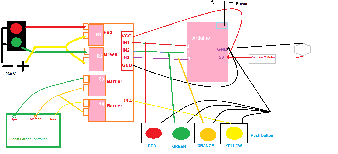
Tragic Light Boom Barrier Control With Arduino Via Ethernet Arduino Project Hub
Parkir Barrier Papan Sirkuit Kartu Controller Untuk Otomatis Boom Barrier Gate Buy Parkir Barrier Papan Papan Sirkuit Untuk Automatic Boom Barrier Gate Controller Untuk Boom Barrier Gate Product On Alibaba Com
Http Files Tecnosinergia Com Fichas Acceso Ax Br26s Manual Pdf
Boom Barrier Connection Diagram Youtube

Understanding Of How The Trigger Connector Works On A Boom Arm Vehicle Barrier Electrical Engineering Stack Exchange
