3 Phase Motor Wiring Diagram 9 Leads. Ford V10 Oil Diagram Reading Industrial Wiring Diagrams.
Sisme Motor Wiring Diagram - If you're searching for picture and video information linked to the keyword you have come to pay a visit to the ideal blog. Our website gives you suggestions for viewing the maximum quality video and image content, hunt and locate more enlightening video articles and images that match your interests. includes one of tens of thousands of movie collections from several sources, especially Youtube, so we recommend this movie that you view. This blog is for them to stop by this website.

Fan Coil Sisme Piris
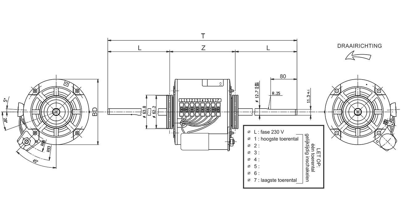
1Ø WIRING DIAGRAMS LN E L1 L2 L3 SC Z2 U2 Z1 U1 Cap.

Sisme motor wiring diagram. Then Do the connection between CB and MC. Starting Stopping of 3-Phase Motor from more than One Place Power Control diagrams. Three Phase Motor Connection StarDelta Y-Δ Reverse Forward with Timer Power Control Diagram.
The first component is symbol that indicate electrical element in the circuit. Then Wire push button wiring OL relay and MC coil which we can call small wiring or control wiring. It shows the elements of the circuit as simplified shapes and the power as well as signal connections between the gadgets.
AC65 AC80 AC90 AC100 three phase motors. Mastertech Marine -- Evinrude Johnson Outboard Wiring Diagrams with 1998 Evinrude Wiring Diagram by admin Through the thousand photos on-line concerning 1998 Evinrude Wiring Diagram picks the top series along with greatest resolution exclusively for you and this pictures is actually among photographs selections in this very best graphics gallery regarding 1998 Evinrude Wiring Diagram. I have a 277480 volt panel.
TERMINAL MARKINGS AND INTERNAL WIRING DIAGRAMS SINGLE PHASE AND POLYPHASE MOTORS MEETING NEMA STANDARDS Dynamic braking resistorBR1 BR2 BR3 BR4 etc. AC80 AC90 AC100 single phase motors. AC80 AC90 AC100 single phase motors.
A three phase motor is more efficient than a single phase motor because of the peculiarities of alternating current ac. OVERLOAD RELAYS AC MOTORS DC MOTORS WIRING CAPACITORS RESISTORS SEMICONDUCTORS Table 1 Standard Elementary Diagram Symbols contd Iron Core Air Core Auto Iron Core Air Core Current Dual Voltage Thermal Magnetic Single Phase 3-Phase Squirrel Cage 2-Phase 4-Wire Wound Rotor Armature Shunt Field show 4 loops Series Field show 3 loops. In the case of the Buildbotics CNC Controller the maximum current is 6 amps for any individual motor port.
DD 4 5 6 7 OAL. Then wire the overload relay with MC. It has quite good efficacy and low manufacture and preserves costs.
LineL1 L2 L3 L4 etc. In the above one phase motor wiring i first connect a 2 pole circuit breaker and after that i connect the supply to motor starter and then i do cont actor coil wiring with Normally Close push button switch and Normally Open push button switch and in last i do connection between capacitor start motor. Control 3-Phase Motor from more than Two buttons Power Control.
Single-Phase Wiring Diagrams ALWAYS USE WIRING DIAGRAM SUPPLIED ON MOTOR NAMEPLATE FOR MOTORS WITH THERMAL PROTECTION Single Voltage Single Rotation Single Voltage Reversible Rotation Dual Voltage Single Rotation Split-Phase Motor Dual Voltage Reversible Rotation Capacitor Motor Single-Phase Wiring Diagrams. The following diagram shows the connections to be made for an 8-wire series connected bipolar stepper motor. 3 Phase Motor Winding Diagram.
Inst Maint Wiringqxd 5032008 1002 AM Page 7. Collection of 3 phase motor wiring diagram 9 leads. November 21 2018 by Larry A.
First of all wire the CB Circuit Breaker but do not switch On. A Three-Phase Asynchronous Motor is the most commonly used motor on earth. 480 volt motor wiring diagram.
This is especially true for larger motors. Field seriesS1 S2 S3 S4 etc. 4 wire reversible PSC motor.
Field shuntF1 F2 F3 F4 etc. Two chief sections of the engine are both rotor and stator. DD 4 5 6 7 OADES Alpha Series Supply D-1315 Diags.
The other thing that you will get a circuit diagram. AS-183 wiring diagram with switch. Exico Electric Motors Limited 4 Stanton Road Finedon Road Industrial Estate Wellingborough NN8 4HN wwwexicocouk Tel 01933 277930 Fax 01933 272184 Wiring Diagram - Single-phase motors 1EMPC - Permanent Capacitor Motors 1EMPCC - Capacitor Start Capacitor Run Motors ELECTRIC MOTORS.
For 3 phase motor controlling diagram and procedure follow the below tips. 4 wire reversible PSC motor with a triple pole double throw switch. On the motor there is a low voltage wiring and a high voltage wiring.
The ford modular engine is ford motor companys overhead camshaft ohc v8 and v10 gasoline powered small block engine family. V 6 Engine Diagram Basic Electrical Wiring Theory. 12 leads terminal wiring guide for dual voltage delta connected ac induction motor.
Bore size is 902 mm 3552 in and stroke is 1058 mm 4165 in identical to the 54 l v8. The above diagram is a complete method of single phase motor wiring with circuit breaker and contactor. Thermal contacts TB white M 1 Z2 - Yellow Z1 - Blue U2 - Black U1 - Red Bridge L1 and L2 if speed controller SC is not required Anti-Clockwise Clockwise These diagrams are current at the time of publication check the wiring diagram supplied with the motor.
1985 Omc Ignition Wiring Diagram. 3 wire 3 phase motor. 40-50 HP with UFI Ignition.
The next diagram shows the connections for an 8-wire parallel connected bipolar stepper. Three Phase Motor Connection STARDELTA Without Timer Power Control Diagrams. N-6 INSTALLATION WIRING DIAGRAMS FAN TROUBLE SHOOTING FANTECH 2016 WIRING DIAGRAMS - STANDARD MOTORS N These diagrams apply to STANDARD FRAME INDUCTION MOTORSwhich are used in the following products-Pgs OADEDV AlphaBeta Series D-46 Diags.
A wiring diagram is a streamlined conventional pictorial depiction of an electrical circuit. There are two things which are going to be present in any Single Phase Motor Wiring Diagram With Capacitor. A circuit is usually composed by many components.

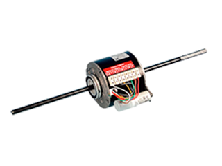
Single Phase Fan Motor Type Sisme
How To Wire 1 Phase 3 Speed Motor Electrical Engineering Stack Exchange

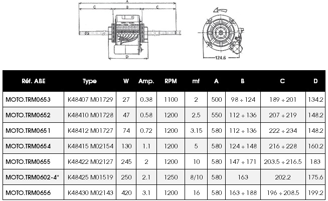
Retour Sisme Moteurs Double Arbre Long 6185000551 Diagram
Fan Coil Electric Motors
Fan Coil Electric Motors

How To Connect Fan Coil Easy 5 Wire Ac Fan Motor Wiring Diagram 3 Speed Youtube Ac Fan Motor Fan Motor Ac Fan
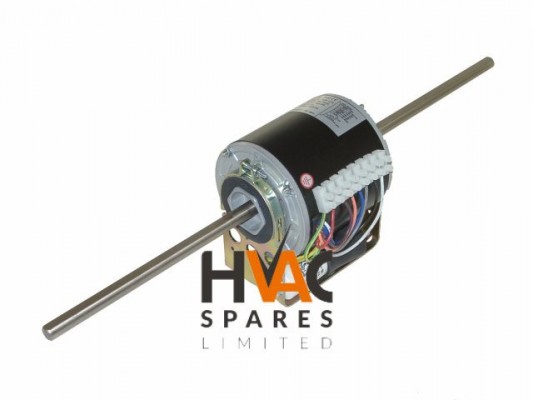
Sisme K48415 M00534 Free Delivery At Hvac Spares Shop

Retour Sisme Moteurs Double Arbre Long 6185000033 Diagram
Single Phase Fan Motor Type Sisme
