A terminal block is provided for wiring the maglock to the power supply and for the Bond Sensor Relay outputs. PORTE analog input voltages cannot exceed VDDIO_E supply when VDD VDDIO_E.
Power Supply Control K80 Wiring Diagram - If you're searching for picture and video information related to the keyword you've come to visit the ideal blog. Our site gives you hints for viewing the maximum quality video and picture content, search and locate more informative video content and graphics that fit your interests. comprises one of thousands of movie collections from several sources, especially Youtube, so we recommend this movie for you to see. This site is for them to stop by this website.

Door Access Control Power Supply K80 For Sale In Santry Dublin From Estmx
Note that all these links are external and we cannot provide support on the circuits or offer any guarantees to their accuracy.
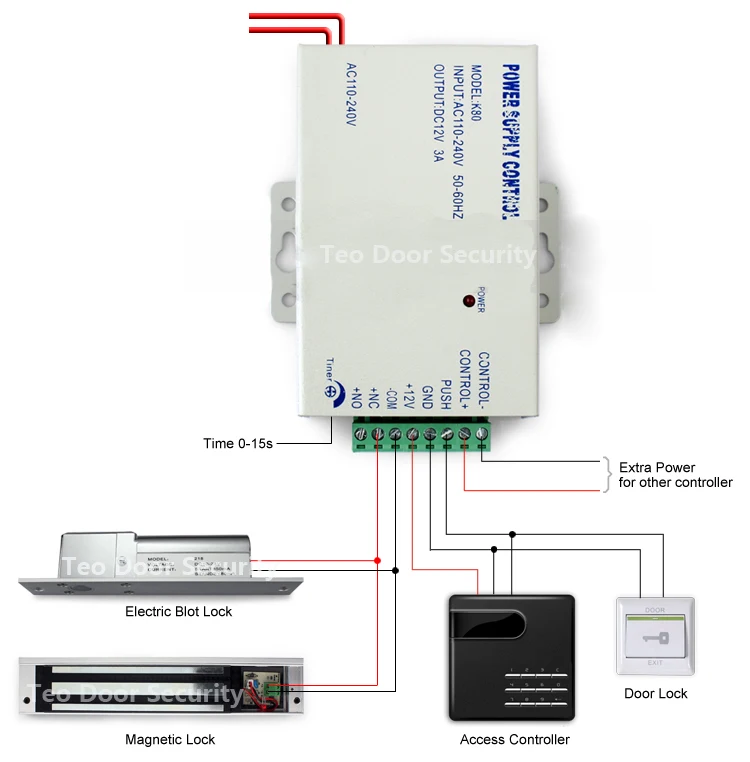
Power supply control k80 wiring diagram. Some circuits would be illegal to operate in most countries and others are dangerous to construct and should not be attempted by the inexperienced. Power Supply for Access Control Board. 3Controls electric lock directly 4Power.
VDD and VDDIO_E may ramp together if tied to the same power supply. ALIGNMENT OF THE MAGLOCK AND ARMATURE PLATE. Wiring Key 1 Brown 2 White 3 Blue 4 Black 5 Gray Note.
Cabled wiring diagrams are shownQuick disconnect QD wiring diagrams are functionally identical. Includes ADC CMP and RESET_b inputs. Based relay control circuit lock time can be adjusted with 0-15 seconds.
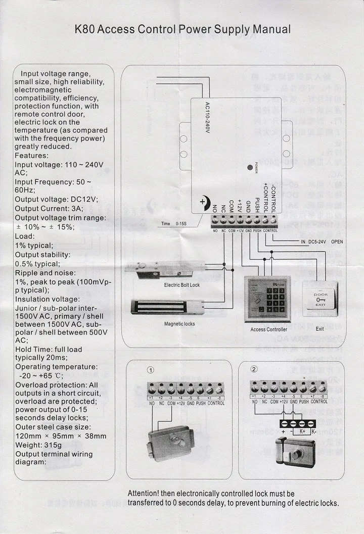
How to install the access control system for home securityTurn to Danmini they got all you need. The VDD domain be powered up before VDDIO_E. Metal 9Outside iron shell dimension120mm95 mm38mm 10Net Weight.
K80 Access Control Power Supply Manual Input voltage range small size high reliability electromagnetic compatibility efficiency protection function with remote control door electric lock on the temperature as compared with the frequency power igreaty reduced. 110 240V Input Frequency. PORTE analog input voltages cannot.
Automatic protection function for dangerous situation. Check the settings of your Wi-Fi network or router. Overload over voltage short circuit.
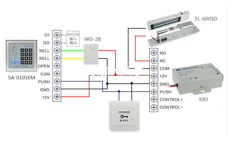
Ripple 90 mA max. Wiring Colour Function Description Pink BELL_A Doorbell button one end Pale blue BELL_B Doorbell button to the other end Green D0 WG output D0 White D1 WG output D1 Grey ALARM Alarm negativealarm positive connected 12 V Yellow OPEN Exit button one endthe other end connected GND Brown D_IN Magnetic switch one endthe other end connected GND. Compatible with EM lock access controller exit push button and RFID reader.
AC180235V 5A Access Power Supply with Backup Battery. 3 PSN-106 PSN-64 PSB-10 5403590 REV A 1209. About Press Copyright Contact us Creators Advertise Developers Terms Privacy Policy Safety How YouTube works Test new features Press Copyright Contact us Creators.
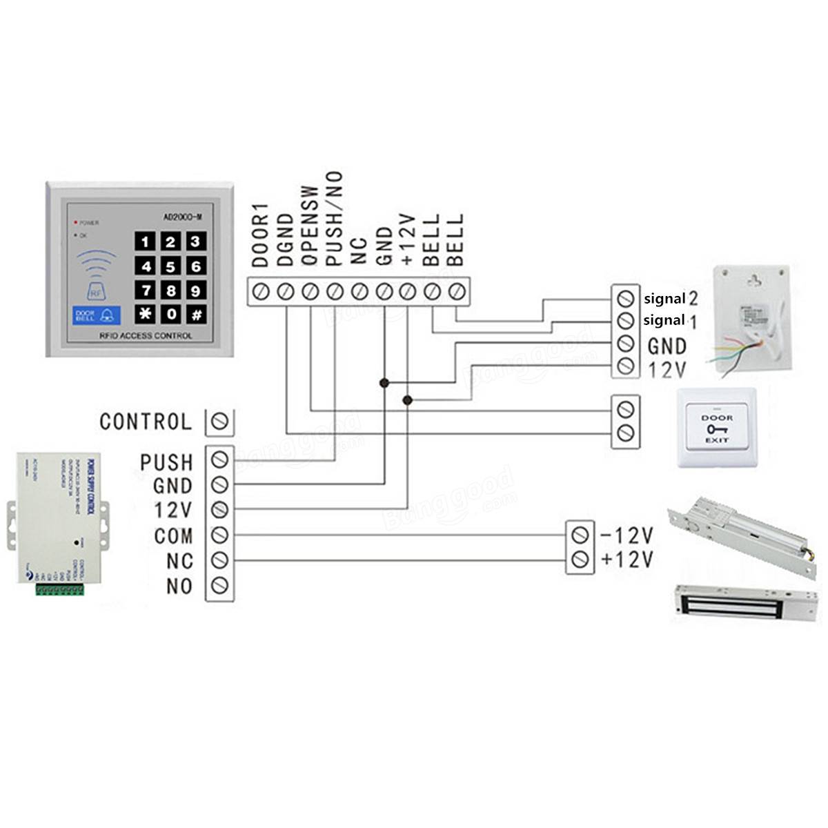
It may be necessary to lift up the board to get to the Green and White wires. Set NC NO outputs can control various types of electric locks Based delay control circuit lock time can be in 0-15 seconds. VDDIO_E must never be higher than VDD during power ramp up or power down.
2 PSN-106 PSN-64 PSB-10 5403590 REV A 1209. The 6-pin plug should be inserted into the 6-pin socket on the access control panel connector. Join The 6-Pin Connectors.
A pair of flying leads are provided for the Door Status Sensor Reed Switch. POTTER ELECTRIC SIGNAL COMPANY LLC St. 1 x Power Supply.
Check whether the camera is warm or cold to the touch. These are the Green and White wires. Specifications Supply Voltage and Current 12 to 30 V dc 10 max.
Can reduce the load of access controller save wiring to reduce the hidden trouble. 05 Typical 6Operating Temperature. Current at 12 V dc exclusive of load 60 mA max.
Make sure that the camera is plugged in and receiving power. -20C65C 7Adjustable Locking Delay. HIGH PERFORMANCE - This power supply can control electric locks or bolts directly Lessen the load of access controller Save project wires Provide very stable and reliable output in a various applications such as lock controlcontroller controlexit buttonRFID-ID Reader.
The interconnector has a 6-pin plug and two power supply sockets. Power supply for door access control is a transformer which provides stable output voltage for access controller electric lock and exit button. Power supply and power control circuit diagrams circuit schematics.
You can follow the steps below to solve problems. Wiring Diagram Electromagnetic Door Lock EM Lock Push Button Power Supply 12v Carane ngonek kunci magnet. Current at 30 V dc exclusive of load.
Diagram from the manual that shows where to connect wires. Make sure this fits by entering your model number.
Power Supply For Access Control System S4a Industrial Co Limited Ecplaza Net

Akses Control Power Supply K80 Saklar Daya Dc 12v 3a Ac 110 260v Untuk Semua Jenis Akses Sistem Kontrol Kunci Pintu Dengan Waktu Tunda Switch Dc Switching Supplyswitch Switch Aliexpress

Buy Amocam K80 Power Supply Control Ac 110 240v To Dc 12v Power Supply For Door Access Control System Video Doorbell Electric Strike Lock Bolt Lock Magnetic Lock Power Supply Controller Online In
New Arrivel More Choose K80 Door Lock Access Control System Machine Power Supply Control Dc 12v 3a Ac 110 240v High Quality Access Control Accessories Aliexpress
Door Access System Electric Power Supply Controller Fans Parts Automotive Ekbotefurniture Com
Power Supply 12v 3a Utk Rfid Access Door Lock Control Switch Mode Shopee Indonesia
New Arrivel More Choose K80 Door Lock Access Control System Machine Power Supply Control Dc 12v 3a Ac 110 240v High Quality Access Control Accessories Aliexpress

Akses Control Power Supply K80 Saklar Daya Dc 12v 3a Ac 110 260v Untuk Semua Jenis Akses Sistem Kontrol Kunci Pintu Dengan Waktu Tunda Switch Dc Switching Supplyswitch Switch Aliexpress

Dc 12v Power Supply Control Switch Door Access Control 2018 Youtube
