Tampering or rerouting of the device wiring harness 4. The first ignition interlock device hit the market in 1988 and after proving to be successful in preventing drunk driving fatalities their use nationwide has increased each year.
Ignition Interlock Device Wiring Diagram - If you're searching for video and picture information linked to the key word you have come to pay a visit to the ideal site. Our site gives you hints for seeing the maximum quality video and picture content, hunt and find more enlightening video content and images that match your interests. includes one of tens of thousands of video collections from several sources, particularly Youtube, so we recommend this movie that you see. It is also possible to contribute to supporting this website by sharing videos and images that you enjoy on this blog on your social media accounts such as Facebook and Instagram or tell your closest friends share your experiences concerning the ease of access to downloads and the information you get on this website. This site is for them to stop by this site.

Electrical Interlocking Wiring Diagram
1 BROWN Start Wire KEY SIDE 2 Start Wire STARTER SIDE 3 BLACK Ground 4 RED Fused 12VDC 5 BLUE Horn Polarity FUSED 12V or GROUND 6 Y YEE LLLLLOOOWW Vehicle Horn 7 ORANGE Flasher Light Polarity FUSED 12V or GROUND 8 VIOLET Vehicle Flashers This wire MUST be.

Ignition interlock device wiring diagram. Here is a basic wiring diagram that applies to all vintage and antique lawn and garden tractors using a stator charging system and a battery ignition system. There are three main components in the switch starting circuit. A wiring diagram is a simplified traditional photographic representation of an electrical circuit.
Intoxalock wiring diagram Ignition interlock rule lets more DUI offenders back on the road earlier. Call 888 283-5899 to schedule your ignition interlock installation appointment and get back on the road today. A simple electrical interlocking control diagram is shown below.
An ignition interlock device is a breathalyzer that is installed into your vehicle to be used to monitor your blood alcohol level. This is unlike a schematic diagram where the arrangement of the components interconnections on the layout generally does not match to the elements physical places in the finished gadget. What is an Ignition Interlock Device.
By offering the most installation locations in the US Intoxalock Ignition Interlock makes the IID installation process simple and convenient. Breathalyzer Ignition Interlock Wiring Diagram 2003 Gmc Stereo How To Bypass An Ignition Interlock Device Breathalyzer Wiring Diagram Wiring Diagram Data Schema. It shows the elements of the circuit as simplified shapes and.
Variety of intoxalock wiring diagram. The line side is the wire that sends power to the unit from the ignition switch along the relay wire. Variety of ignition interlock wiring diagram.
The usual elements in a wiring diagram are ground power supply cable as well as link output devices buttons resistors logic gate lights and so on. Section 2 - Intoxalock Legacy relay diagram non camera 7Wiring Diagram. An ignition interlock device is comprised of a few different pieces.
A wiring diagram is the roadmap for a particular circuit. Our technicians have a wiring diagram of your particular vehicle so they know exactly where to find the wires they need to install the device. Once the Device wakes up and the WAIT light glows orange turn the key back to the OFF position.
Architectural wiring diagrams take effect the approximate locations and interconnections of receptacles lighting and unshakable electrical facilities in a building. Disconnecting the interlock handheld device except for regular recalibrations or device swaps or to remove from extreme temperature conditions as explained later. Smart start s spanish ignition interlock ssi 1000 ssi 20 20 training video.
About Press Copyright Contact us Creators Advertise Developers Terms Privacy Policy Safety How YouTube works Test new features Press Copyright Contact us Creators. Handheld unit Mouthpiece Relay cord connecting the device to your vehicle Camera unit if required to have by your state. Ignition Interlock Wiring Diagram Collection.
The wires needed are generally found within the cabin of the vehicle. To interconnect the motor circuit in such a way in which the second motor will not start until the first one run likewise the third one motor will not run unless the second one run and so on. If so the wires are delicately fed through an existing grommet or entry point in the vehicles firewall.
Occasionally in newer vehicles they are located under the hood. To interconnect the motor circuit. Ignition interlock wiring diagram wiring diagram centre.
A wiring diagram typically provides details about the loved one placement as well as setup of devices and also terminals on the tools to assist in building or servicing the tool. Motor circuit connection is called interlocking. Interconnecting wire routes may be shown approximately where particular receptacles or fixtures must be upon a common circuit.
Basic ignition system wiring diagram. Smart Start Ignition Interlock Device Manuals Ssi 20 30 Smart Start Inc Rgb Color Model Ignition Interlock Device Wiring Charging Or Changing Your Car Battery With An Interlock Device Smart Start Ignition Interlock Device Manuals Ssi 20 30 Smart Start Interlock Wiring Diagram Wiring Library Ssi 20 20 20 30 User Guide 1300 256 900 Manualzz. Mobile ignition interlock device installation.
Opening the plastic device casing 5. Wiring Diagram Images Detail. TIME TO TEST You must complete a breath test that indicates your Breath Alcohol Content BrAC is.
The first step is turning your ignition switch to the ON position. Click on the image to enlarge and then save it to your computer by right clicking on the image. If you have an interlock device installed you will need to submit to a breath test before you can start your car.
Assortment of ignition interlock wiring diagram. It reveals the elements of the circuit as streamlined forms and the power and also signal links between the gadgets. This can be tested by holding the key in the spring loaded position third position of the ignition and tested until you find the wire that is conducting current and it should be obvious which wire is the load side or wire from the unit to the starter relay.
Ignition Interlock Wiring Diagram. A wiring diagram is a streamlined conventional pictorial representation of an electrical circuit. Cutting or destroying any tamper seals on the device 3.
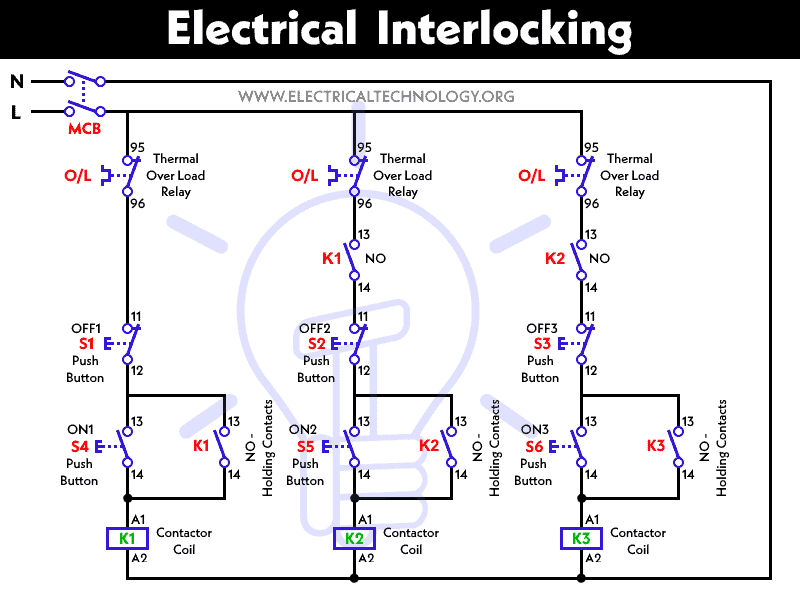
Diagram Wiring Diagram Of Interlock Full Version Hd Quality Of Interlock Avdiagrams Fanofellini It

Ignition Interlock How It Works Installation Or Remove Interlock Bypass Youtube

How To Bypass Smart Start Ignition Interlock Devices Lagu Mp3 Mp3 Dragon

How To Bypass An Ignition Interlock Device
18 Electrical Door Interlock Wiring Diagram Wiring Diagram Wiringg Net Wiring Diagram Door Locks Magnetic Door Lock

Interlock Unduh Gratis Ignition Interlock Perangkat Pintar Mulai Inc Wiring Diagram Elektronik Ignition Interlock Perangkat Gambar Png

Diagram Wiring Diagram For Smart Start Interlock Full Version Hd Quality Start Interlock Msdiagram Strabrescia It

Intoxalock Certification Guide Pdf Free Download

Diagram Based Ignition Interlock Device Wiring Diagram Intoxalock Wiring Diagram
