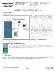
These units are intended only for release of a magnetic lock from the inside of a door. If the customer has an.
Eeb3n Exit Button Wiring Diagram - If you're looking for video and picture information linked to the keyword you've come to visit the ideal site. Our site gives you suggestions for viewing the maximum quality video and image content, hunt and find more enlightening video content and images that match your interests. includes one of tens of thousands of movie collections from various sources, particularly Youtube, so we recommend this video for you to see. This blog is for them to stop by this website.
Securitron Eeb2 Eeb3n Exit Button With Integrated Timer Access
1 the wiring cables from the access control card reader to the access controller.

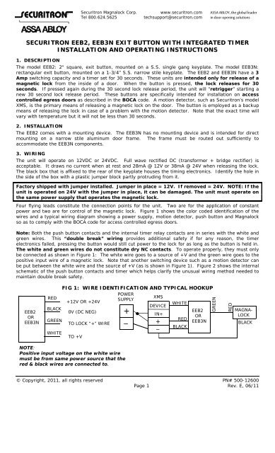
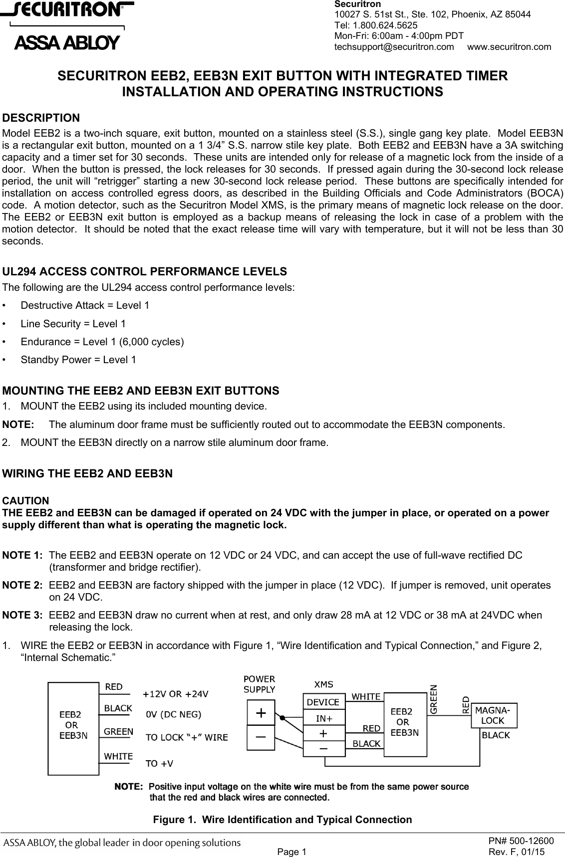
Eeb3n exit button wiring diagram. Pressing the code compliant push to exit push button will bypass the keypad and motion. These units are intended only for release of a magnetic lock from the inside of a door. Single Gang or Narrow Stile.
Activating the request to exit rex motion sensor will unlock the magnetic lock allowing the door to be opened. You can also view all Wiring Diagrams by leaving the fields blank and clicking the Search button. Push to exit buttons mainly come in two types.
The lock will disengage thus opening the door as required. When the button is. Exit Button Such as Securitron EEB2 Note.
The button is field selectable at 12 or 24VDC to match the voltage of the triggered lock. Momentarily pressing the button releases door for 30 seconds. In most cases dc power can be used continuous duty indefinite.
Request To Exit Wiring Diagram. These units are intended only for release of a magnetic lock from the inside of a door. Securitron EEB2 EEB3N Installation and Operating Instructions Installation Instructions.
Rectangular exit button mounted on a 1-34 SS. Securitron AQDR Data Sheet. Search Wiring Diagrams for HES and Securitron products.
The EEB2 and EEB3N have a 3 Amp switching capacity. Model EEB3N is a rectangular exit button mounted on a 1 34 SS. Mounted next to door.
Using a wireless transmitter and receiver to release an electromagnetic lock. If the button does not release the door. Narrow stile key plate.
Emergency Exit Buttons offer additional safety as required by code for possible malfunction of motion exit sensor. Use the fields below to narrow down your search. Also the access control system wiring diagram includes a lot of wiring systems like magnetic door lock wiring diagram push to exit button wiring diagram electric door strike wiring diagram and magnetic door lock wiring diagram and etc.
Push Button Switch Wiring Diagram Clipsal Toyota Dimmer Diagrams. With this the door automatically releases and allows free exit. Showing posts with label request to exit button wiring diagram.
Both EEB2 and EEB3N have a 3A switching capacity and a timer set for 30 seconds. Regular wall-mount push to exit buttons. Motion sensors can take over the job of push to exit buttons.
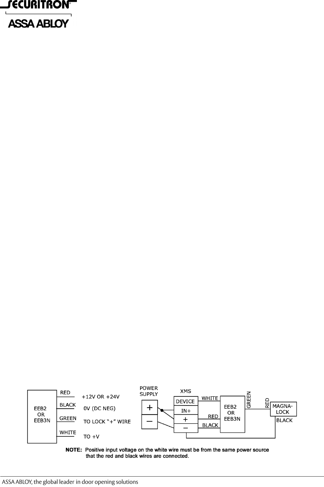
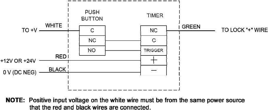
DESCRIPTION identification of the wires and a typical wiring diagram showing a power supply motion detector customer within 24 hours of SECURITRONs receipt of the product from customer. Request to exit button wiring diagram request to exit motion wiring diagram request to exit wiring diagram. Sheet of 1 1 are not necessary but helpful.
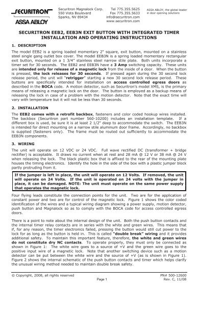
The model EEB3N is a spring loaded momentary rectangular exit button mounted on a 1 34 stainless steel narrow stile plate. The exit button releases power to the magnetic lock. Backup devices in case of exit sensor failure per BOCA NFPA NBC and VBC code.
Push To Exit Button The Ultimate Guide By Kisi Written By nash Thursday September 12 2019 Add Comment Edit. Jason R Clement Version. 1 the wiring cables from the access control card reader to the.
Typical wiring diagrams for push button control stations 5 explanation of symbols momentary contact push button auxiliary contacts operate when operating coil of contactor. A crucial step in setting up your push-to-exit button is properly wiring all the components. When the button is pressed the lock releases for 30 seconds.
EEB2 Installation Manual EEB2-InstallationManual EEB2 - Securitron. SECURITRON EEB2 EEB3N EXIT BUTTON WITH INTEGRATED TIMER INSTALLATION AND OPERATING INSTRUCTIONS 1. Operates on 12 or 24 VDC must be same voltage as the installed lock For indoor use only.
Emergency Exit Button 1224 VDC 3A 45 Length x 175 Width x 3 Depth Includes 30 Second Timer Narrow Stile Switchable GreenRed Lens. Typical wiring diagrams for push button control stations 3 genera information at each circuit is illustrated with a control circuit continued schematic or line diagram and a control station wiring diagram. 2 green square push button labeled push to exit swich mounted on single gang wallplate.
The EEB2 and EEB3N have a 3 Amp switching capacity and a timer set for 30 seconds. Securitron EEB3N - 1 x 34 Rectangle Emergency Exit - 30 Sec Timer - Narrow Stile - GreenRed Lens. MFR PART EEB3N.
At a minimum voltage and D0D1 must be connected to the IPBridge. The following diagram outlines the setup with an electric strike lock. The Beeper and Green LED IPBridge Power Supply with Magnetic Lock Exit Motion Exit Button and Door Contact DwgNo.
Both units incorporate a timer set for 30 seconds. Eeb2 wiring diagram Keyword Found Websites Listing. The EEB2 can be used as a backup access control device in the event of an exit sensor failure.
Includes switchable green red and blue ADA lenses. Mounted next to door. The device is mounted on a stainless steel single-gang faceplate and features internal double-break wiring.
In an IP system like Kisi this will involve the door lock the access reader the controller the power supply and the push-to-exit button as well as optional contact sensors. SPDT 3 Amp wet NC contacts. Emergency Exit Buttons offer additional safety as required by code for possible malfunction of motion exit sensor.
Securitron Eeb2 Eeb3n Exit Button With Integrated Timer Access
Securitron 500 12600 F Eeb2 Eeb3n Installation And Operating Instructions Eeb2 Io 12600 F

Securitron Eeb2 Eeb3n Emergency Exit Buttons Taylor Security Lock
Securitron 500 12600 F Eeb2 Eeb3n Installation And Operating Instructions Eeb2 Io 12600 F
Securitron Eeb2 Eeb3n Exit Button With Integrated Timer Access
Https Www Openingsstudio Com Aaos Aaos Cutsheetview Jsp Id 16609186
Securitron Eeb2 Eeb3n Exit Button With Integrated Timer Access
Securitron Eeb2 Eeb3n Exit Button With Securitron Magnalock
Securitron 500 12600 F Eeb2 Eeb3n Installation And Operating Instructions Eeb2 Io 12600 F
