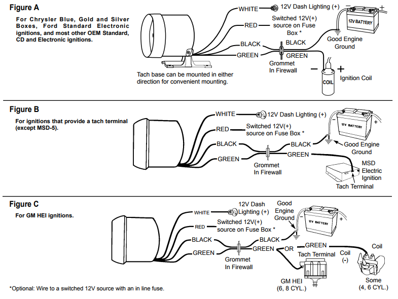
Pressure sensor wire is included in the package of the product. Black Ground Defi black wire should go to the black wire on the radio harness.
Defi Rpm Gauge Wiring Diagram - If you're looking for picture and video information related to the keyword you've come to visit the right site. Our website provides you with hints for viewing the maximum quality video and picture content, hunt and find more enlightening video content and graphics that match your interests. comprises one of tens of thousands of movie collections from several sources, especially Youtube, so we recommend this video that you view. It is also possible to contribute to supporting this website by sharing videos and images that you like on this site on your social networking accounts like Facebook and Instagram or educate your closest friends share your experiences concerning the ease of access to downloads and the information that you get on this website. This site is for them to stop by this site.

Diagram 5 Inch Tach Wiring Diagram Full Version Hd Quality Wiring Diagram Avdiagrams Fanofellini It
Its intended to aid all the average person in developing a suitable method.

Defi rpm gauge wiring diagram. Tibalah pula proses wiring power source controller unit gauge defi ini. Autometer Pro Comp Ultra Lite Wiring Diagram Fresh Auto Meter Wiring Autometer Gauge Wiring Diagram. 2Red emitting needle pointer Gauge dial illumination and a red emitting needle pointer increase visibility.
Wire putih controller iaitu wire dimmer yang perlu di tap pada wire lampu kecil bawah dashboard iaitu wire berwarna hijauputih. Wiring Diagram Ignition harness Fuse box Red Ignition 12V Green RPM signal input Ignition harness Fuse box. Now youll be connecting the BLACK DEFI Control Unit wire to pin 4 on the 80 pin E9 plug.
When connecting the IG Power Engine RPM Ground Vehicle Speed signal wires to the ECU be sure to check the Connection Diagram 1-4 for proper connection. Wiring Diagram arrives with several easy to follow Wiring Diagram Guidelines. Wire oren controller accignition di tap pada wire ignition iaitu wire biruputih atau biru hitam pada wire kunci kereta.
RED tap to RPM wire of your cars RPM gauge. Akhir sekali ialah wire. On Defi Rpm Gauge Wiring Diagram.
Fuel pressure sensor wire 25m PDF00803H for Defi-Link series. Which wire it is you have to find it using digital multimeter google it on how to find rpm wire with digital multimeter. This wiring diagram booklet is designed for use with the.
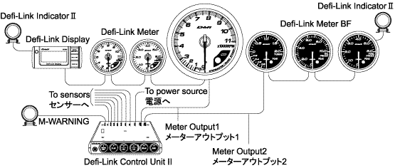
A wiring diagram is a streamlined standard pictorial representation of an electrical circuit. ADVANCE System from 2009 and Defi-Link System from 1998 are not compatible. To 12V battery wire When the RPM signal wire is connected to Defi-Link Control Unit II or Defi-Link Control Unit 2 warning levels can be set in Black Yellow INTAKE MANIFOLD PRESS.
Wiring diagram for aftermarket tachometer a tachometer is gauge to measure mechanical speed in units of rpm revolutions per minute or rotations per minute. Once the ignition switch is turned on a clear display appears by colored LED illumination. Also check P16 for vehicle specific information.
Another wire from sensor is RED connect it to key ON refer to vacuums wiring diagram. Control unit and sensor wires for Defi-Link System cannot be used for ADVANCE System except some common sensors and extention wires. To operate Defi-Link gauges and displays Defi-Link Control Unit II is necessary.
Do not install gauges into the passenger side or center of the dashboard. Sensor cable from the gauge will have two wires in it that is RED and BLACK and cable from sensor will have three wires that is WHITE BLACK. Illumination 12V Defi white wire should go to the violet wire on the radio harness.
Ignition 12V Defi orange wire should go to the green worange stripe on the AC harness. Find product manuals and wiring diagrams for your auto meter product. The system is also designed to allow all sensors to be attached to the control unit II so that gauges can be mounted separately without the need for multiple tubing or wiring to each gauge.
Pressure sensor wire 3m PDF05604H for DIN-Gauge. If after completely reading these instructions you have questions regarding the operation or installation of your instruments please contact auto meter technical service at 866 248 6357. You must make sure this wire supplies constant power to the DEFI Control Unit otherwise youll be spending a lot of time programming your gauges at every startup.
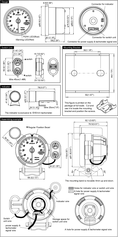
When using pressure sensor pressure sensor wire is necessary. This is a power supply for the sensor. Tachometer gauge Wiring connector Fitting instructions 1.
These guidelines will be easy to understand and apply. A wiring diagram is a simple visual representation of the physical connections and physical layout of an electrical system or circuit. A Japanese operation manual a wiring manual and a questionnaire card Quantity.
Diagram Rpm Gauge Wire Full Version Hd Quality Gwendiagram Premioraffaello It Digital Boost Vac Gauge Installation Instructions 2650 1236 00 Manualzz How To Install Defi Boost Gauge. Wiring configuration is different than most Tachometers20150213 200330 About Press Copyright Contact us Creators Advertise Developers Terms Privacy Policy Safety How YouTube works Test. If you using kancilstock kancil gauge with RPM just follow the diagram behind the kancils gauge have to take out the whole gauge and find wire that goes to the RPM.
Want to install greddy rpm gauge in diagram dolphin gauges wiring digital tachometer 52mm small defi white advance bf oil pressure sirus series meter 7 mitsubishi lancer and evolution for car how a 8 steps emanage my trust profec map rhdan sirius vision ultimate installation manual coleman pop up camper harness water temp multi d dauge hks turbo timer universel plug instruction basic electrical diagrams. The wire you want here is PIN 33 on the 40 pin E10 plug shown below. Terdapat 4 wire utama yang perlu di tap pada wire kereta iaitu wire merah di tap pada wire constant 12v iaitu pada wire kunci berwarna putih.
Connect it as picture 3 below or just follow the male-female coupling. Features of Defi-Link Meter BF a1LED illumination Gauge dials are invisible while the ignition switch is off. Switch unit wire 45cm ft.
Will move to highest RPM to clear highest RPM press CLEAR button while highest RPM. Buy esupport car 2 52mm tacho gauge meter kit rpm automotive. Constant 12V Defi red wire should go to the blue w red stripe wire on the radio harness.
Sensor attachment commercially available is necessary to install sensor.

Diagram Wiring Diagram Rpm Meter Full Version Hd Quality Rpm Meter Odiagrami Fanofellini It

Draw Your Wiring Rpm Meter Diagram

Defi Advance A1 Defi Link System Daisy Chain Auto Gauge Zd 6 Alat Pengukur Volt Suhu Air Suhu Minyak Minyak Tekan Tachometer Rpm Turbo Temp Air Gauge Aliexpress
Defi Link System Features Defi Exciting Products By Ns Japan

Diagram Wiring Diagram Tachometer Defi Full Version Hd Quality Tachometer Defi Trudiagram Mbreporter It
Racer Gauge Specifications 3 1 8in 80mm Tachometer Defi Exciting Products By Ns Japan
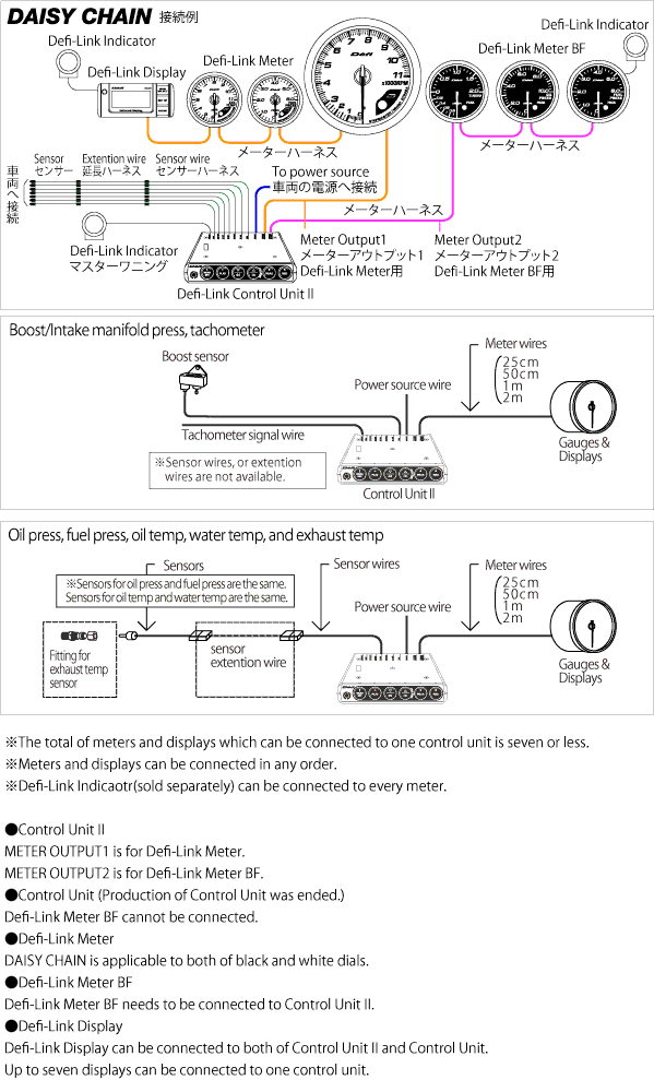
Defi Link System Connection Defi Exciting Products By Ns Japan
How To Install A Tachometer Onallcylinders

Wiring Diagram Rpm Gauge For Android Apk Download
