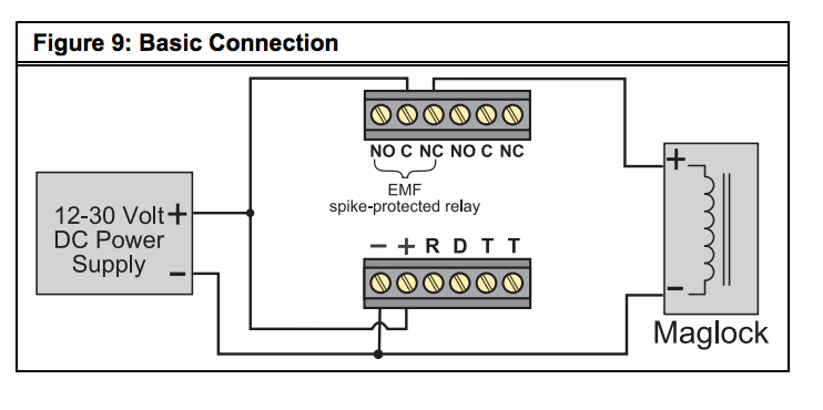
Push to exit button wiring diagram. Request To Exit Maglock Wiring Diagram Cabinetdentaireertab Com In most cases that will be the keypad push to exit button motion sensor and kisi.
Request To Exit Motion Wiring Diagram - If you're looking for video and picture information linked to the keyword you've come to visit the ideal blog. Our site provides you with hints for viewing the maximum quality video and picture content, hunt and find more enlightening video articles and graphics that match your interests. comprises one of thousands of movie collections from several sources, particularly Youtube, therefore we recommend this movie for you to see. This blog is for them to visit this website.
Bosch Fire Alarm Wiring Diagram
The Pin out is described below.

Request to exit motion wiring diagram. The options are all shown in the fail safe mode. The unlock time will be configured by the motion sensor dip switch settings. 800004 - Wizard System.
Aim the detector for the desired coverage. Push to exit button wiring diagram. Request to Exit REX or Remote Unlock Button Wiring.
800005 - Wizard System w Interface Motion Presence. Wiring is shown in figure 5. Mower Wire Diagram Online Wiring Diagram The contacts are ul listed with 10 amp capacity.
RCR-REX Request-to-Exit Dual Technology Motion Sensor Installation Instructions 2 Wiring This section provides examples of different wiring options. 52 Timer Reset Mode - Switch 2 Switch 2 ON - The relay timer starts when the detector sees motion and restarts if there is additional motion. They are mounted right over the door at the inside of the door frame.
In general a Motion Detector or a maual override should be connected to the REX input. Passive Infrared Request to Exit Device. The DS160161 is UL Listed as an access control device under the UL 294 Standard and is listed for Class I for UL Canada under ULC-S319.
Push to exit button by enforcer brandmotion sensors. Use the fields below to narrow down your search. Mower wire diagram online wiring diagram the contacts are ul listed with 10 amp capacity.
See all applications. Pdf 1495 KB. There are additional filters on the Results page to.
The XMS Passive Infrared Request to Exit Device is a motion detector specifically designed to reliably release magnetic locks. Coil excess wiring behind the back cover along the. Mount the detector module to the back cover.
When this input is closed the access system will operate its lock control relay to release the lock and will not create an alarm signal as it will consider the exit event a legal one. Activating the Request-to-Exit REX motion sensor will unlock the magnetic lock allowing the door to be opened. A motion detector such as securitron s model xms is the primary.
System should have a two-terminal REX request to exit input. The Camden CM-RQE70 uses a plug-in wiring harness for all electrical connections. Pressing the code compliant Push to Exit push button will bypass the keypad and motion.
Switch 1 ON - LED operates normally when motion is detected. Two wires - will power the LED on the button for the backlight and two wires C-NC or C-NO will serve as signal wires that connect to the rest of. Request To Exit Wiring Diagram carbatteryrecyclingi 6 volt rv battery wiring diagram cb51446 Volt Rv Battery Wiring Diagram Can New Car.
Designed to reliably release magnetic locks. Sort by 800390 - 10ACP12DS Access control package 5. Switch 1 OFF - LED is turned off.
Search Wiring Diagrams for HES and Securitron products. Alarm Panel Wiring diagram. In most cases dc power can be used continuous duty indefinite.
You can also view all Wiring Diagrams by leaving the fields blank and clicking the Search button. 1 the wiring cables from the access control card reader to the access controller. DS160DS161 Installation Guide High Performance Request-to-Exit Sensors 10 Description The DS160161 is a passive-infrared PIR detector designed for Request to Exit REX interior applications.
Power supply may be ac or dc depending on the requirements of the strike. Loosely mount the back cover to the mounting surface using the supplied mounting screws. Activating the request to exit rex motion sensor will unlock the magnetic lock allowing the door to be opened.
With this the door automatically releases and allows free exit. If motion continues the relay will activate for another full cycle. A person approaching the door is seen by the motion detector just before reaching the door.
The exit button releases power to the magnetic lock. Remote Programming Interface RPI Wiring. 2 green square push button labeled push to exit swich mounted on single gang wallplate.
For surface wiring use the break out wiring entrance on the front cover at the same end as the wire entrance. Basic hook-up Figure 4 shows the basic hook-up for the RCR-REX a power supply and a magnetic lock. Motion Detector Wiring.
The lock will disengage thus opening the door as required. The relay only drops out when there is no more motion. When the sensor sees motion power.
Wiring is shown in Figure 5. Push to exit buttons mainly come in two types. If the door is opened the Relay On Time is reduced to 2 seconds.
Motion Presence Parallel On Analog Controls W LO-21. The typical REX button has 5 wires - COM NO NC although only 4 are needed for normal operation. Regular wall-mount push to exit buttons.
Request to exit motion wiring diagram. System should have a two terminal rex request to exit input. Screw the plate into the back box taking care not to crimp the wires.
Should be connected to the Normally Open contact of the Exit button. Camden CM-RQE-70 Request-to-Exit Sensor is a passive infrared PIR. Essex electronics stainless steel vandal resistant request to exit buttons can be used to control an automatic door electric lockstrike magnetic.
Code Compliant Access Controlled Egress Door Manualzz
Relay Connection Wiring Diagram Relay Emergency Lighting Electrical Circuit Diagram
Wiring And Configuring A Rex Device Prodatakey Inc
Low Volt Wiring Unit 4 School Of Lock And Electronic Security
External Power Supply Fail Safe Electric Lock With Rex Motion Sensor Kisi Support
Diagram Examples Chanish Org Winch Solenoid Diagram Wiring Diagram
Low Volt Wiring Unit 4 School Of Lock And Electronic Security
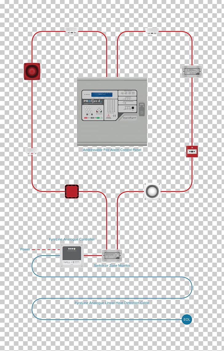
Fire Alarm Control Panel Fire Alarm System Heat Detector Security Alarms Systems Wiring Diagram Png
Es200 Wiring Diagram Connection Scheme In 2021 Automatic Sliding Doors Diagram Automatic Door


