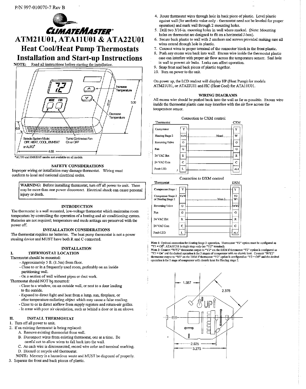
MonitorConfigure Installers can configure units from the iGate communicating thermostat or configurationdiagnostic tool including. WIRING DIAGRAMS All excess wire should be pushed back into the wall as far as possible.
Climatemaster Thermostat Wiring Diagram - If you're looking for picture and video information linked to the keyword you've come to visit the right blog. Our website provides you with hints for seeing the highest quality video and image content, hunt and find more informative video articles and images that match your interests. comprises one of thousands of movie collections from various sources, especially Youtube, so we recommend this movie for you to view. This site is for them to stop by this website.
Climatemaster Ata11u01 Ata22u01 Atm21u01 User Manual Manualzz
Earth-ground couple to the chassis ground screw is provided in the control box.

Climatemaster thermostat wiring diagram. Click Products in the main navigation 2. The way you described yours diff 1 for first stage diff 2 for second stage and diff 2 for third stage keeps aux heat off until room temp drops to 66 degrees. Click the Wire Diagrams tab in the middle of the page 5.
Thermostat wire Be sure it is not running parallel along power wire. Packaged Units iGate Communicating Thermostat Connection to DXM2 Control iGate Thermostat ATC32U03 24Vac Hot DXM2 24V Comm A Comm - B-B-OD ID GND Outdoor Sensor. Off HP Stat with B output with heating.
Thermostat Connections Thermostat Connections C 24V Common for Control Circuit R 24V Supply for Control Circuit A Communications Positive. C is known as the common terminal. Select the product family packaged systems vertical stacks etc 3.
This is a brand new Original Equipment Manufacturer OEM ClimateMaster Carrier water source heat pump ECM motor wiring harness part 11B0012N01. Heat pump thermostat wiring - A typical wire color and terminal diagram. Select Control CXM DXM2.
ElectricalLow Voltage Wiring 30 ElectricalThermostat Wiring 31 Wiring Diagrams 3233 ECM Blower Control 34 Blower Data 35 DXM2 Controls 36 DXM2 Layout and Connection 37 Unit Commissioning And Operating Conditions 38 Unit Start-Up and Operating Conditions 39 Unit Start-Up Procedure 4041 Unit Operating Conditions 4243. BACnet MSTP Johnson Controls N2 and Modbus. To connect the thermostat to the unit.
Dehumidification Mode - Provides selection of normal or Dehumidification Fan Mode. This part is used in but not limited to the following models. Design the depth of the trap water-seal based upon the amount of ESP capability of the blower where 2 inches 51mm of ESP capability requires 2.
Etc 2 A output can be used for any 24Vac load 20VA max. 3 Use W input for Electrical Heat. The MultiProtoCol MPC Heat Pump controller is designed to allow the integration of water source heat pump equipment into DDC systems.
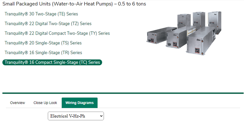
Select the product series TC TE TSM etc 4. Declare your personal energy independence. This will reset the thermostat.
As shown in the diagram you will need to power up the thermostat and the 24V AC power is connected to the R and C terminals. All wire diagrams arenow nested in the individual product pages. Attach the iGate Connect thermostat to the.
These two connections will ensure that there is power to the thermostat that you are operating. Thermostat Type OB - Provides selection of thermostat type. Connections in the control box.
Heat pump thermostats with O output on with Cooling or B output on with Heating can be selected. Use copper conductors only. Thermostats and Accessories ClimateMaster offers a wide range of robust and attractive thermostats from entry level 24V thermostats to simple to use fully featured communicating thermostats that provide the ability to setup and monitor the performance of your water source heat pump without having to go through the complexity of attaching gauges in the field.
Ensure all wiring is landed properly on both DXM2 and thermostat. Refer to the wiring diagram attached to the unit. Replace board if current board still does not function Disconnect and reconnect the wires from the DXM2.
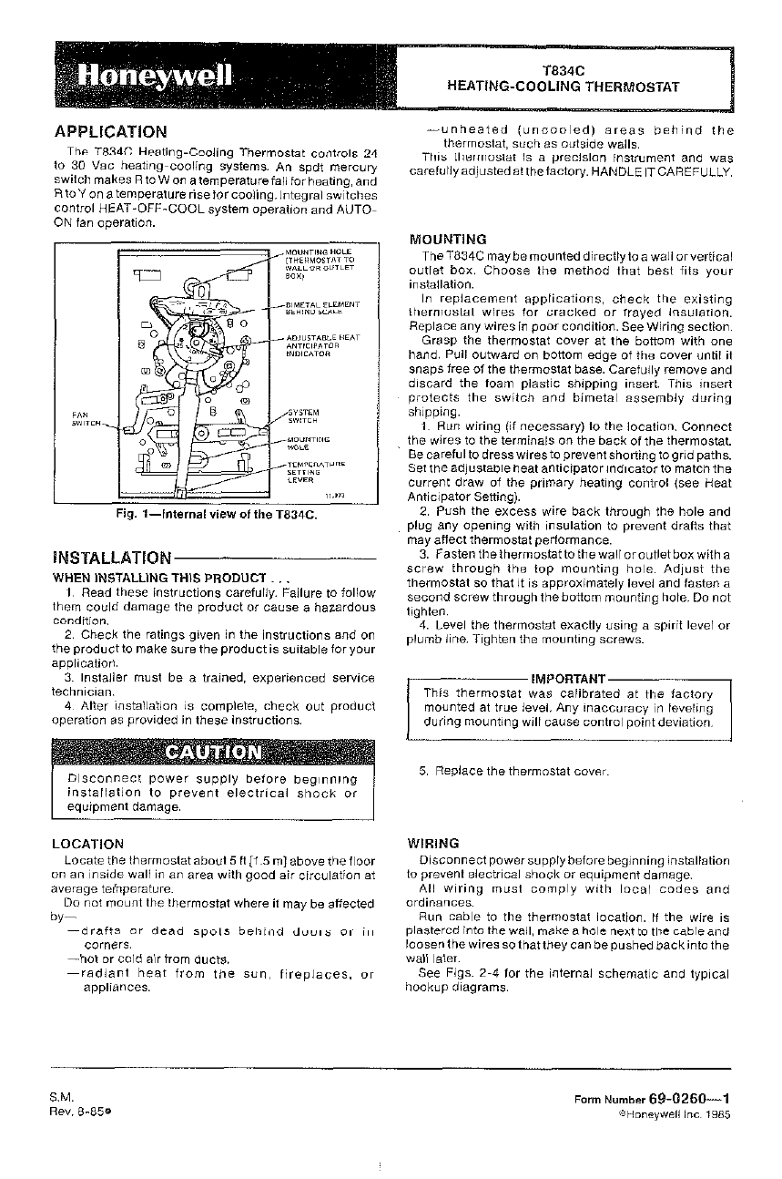
Standard CXM with Thermostat Standard CXM With Thermostat Notes 1 LED on thermostat used for lockout signal and Lockout type HPcode2. Diagram Honeywell Heat Pump Thermostat T874n1016 Wiring Full Version Hd Quality Curcuitdiagrams Volodellaquilabasilicata It. Replaces the following part s.
Air flow loop ΔT water-flow option configuration unit configuration accessory configuration and demand reduction optional to limit unit operation during peak times. ATC32U03 iGate Communicating Thermostat Three-Stage Heat Two-Stage Cool Programmable See equipment wiring diagram for more details. ClimateMaster NET - SHIELD NET ASW13 24 Vac GNDC Lstat Rnet HOTR POLARITY SENSITIVE DDC COMM NETWORK CONTROL BOX LAYOUT LOW SIDE MPC OPTION BOARD WIRING CXM DXM FOR LOW VOLT CONTROL SEE PRIMARY WD OR DXM2 TB1 9X 1 2 3 TB1 3X Capacitor MPC2.
Users can look up the current system status. That is your set-point minus the total of all differentials or 71 - 1 2 2 66. Connect the Wiring You need to use lowvoltage cable to connect the thermostat to the Trilogy Unit.
Verify that the DXM2s dipswitches are set properly. The color of wire R is usually RED and C is BLACK. Electrical V-Hz-Ph 208-230601 265601.
On your keyboard Press Ctrl F to. Connect a ground wire from the power source. Refer to MPC installation application and operation manual for control wiring to the unit.
ClimateMaster Carrier ECM Motor Wiring Harness 11B0012N01. Is the unit properly. Differential settings for most and perhaps all Climatemaster thermostats are cumulative.
Install condensate trap at each unit with the top of the trap positioned below the unit condensate drain connection as shown in Figure 6. Select your voltage and controls. Select Control CXM DXM2.
Fasten the backplate to the wall using the screws provided or other suitable screws. Connect the wires as shown in the wiring diagram. Temperature sensor readings and operational.
On HP Stat with O output with cooling. Do not run the AC power wiring in the same conduct with low voltage wiring. The MPC Controller has the ability to communicate through a choice of three widely used protocols.
Excess wire inside the thermostat plastic case may interfere with the air fl ow across the temperature sensor.
Climatemaster Atm11h02 User Manual Manualzz
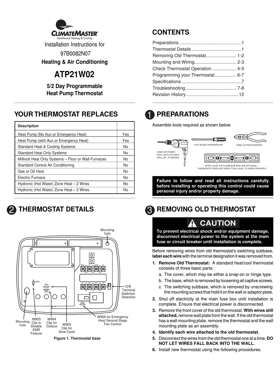
Climatemaster Atp21w02 Installation Instructions Manual Pdf Download Manualslib
Climatemaster Igate Atc32u02 Installation Manual Manualzz
Install Manual Climatemaster Manualzz
Climatemaster Tranquility Tch Series Installation Operation Maintenance Pdf Download Manualslib
Wiring Diagrams
Climatemaster Tyh V 024 060 60hz Hfc 410a Installation Operation Maintenance Instruction Pdf Download Manualslib
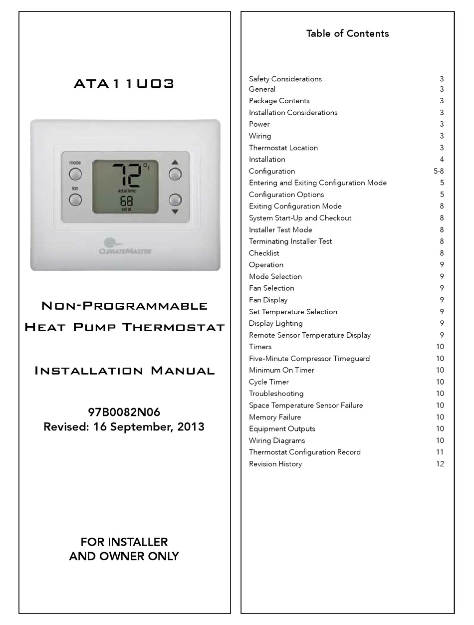
Climatemaster Ata11u03 Installation Manual Pdf Download Manualslib
Ebstatsi01 Smart Thermostat User Manual Climate Master Revised Ecobee Orporated
