Local and national electrical codes and requirements. Switches do not include face plates.
Wattstopper Lvsw 101 Wiring Diagram - If you're looking for picture and video information linked to the key word you have come to visit the right blog. Our site gives you hints for seeing the highest quality video and picture content, search and find more enlightening video content and graphics that match your interests. includes one of thousands of video collections from several sources, particularly Youtube, therefore we recommend this video that you view. You can also bring about supporting this website by sharing videos and graphics that you like on this site on your social networking accounts like Facebook and Instagram or educate your closest friends share your experiences about the simplicity of access to downloads and the information you get on this site. This site is for them to visit this website.

Wattstopper Lvsw 101 I 1 Button Low Voltage Wall Switch 24v Ivory Prolighting
Current Rating 30 Milliamp Per LED UPC.
Wattstopper lvsw 101 wiring diagram. BLUE wire from power pack to. Wattstopper Switch LVSW-101 Installation instructions 2 pages 9. RED wire 24VDC from power pack to the 24V terminal on the sensor.
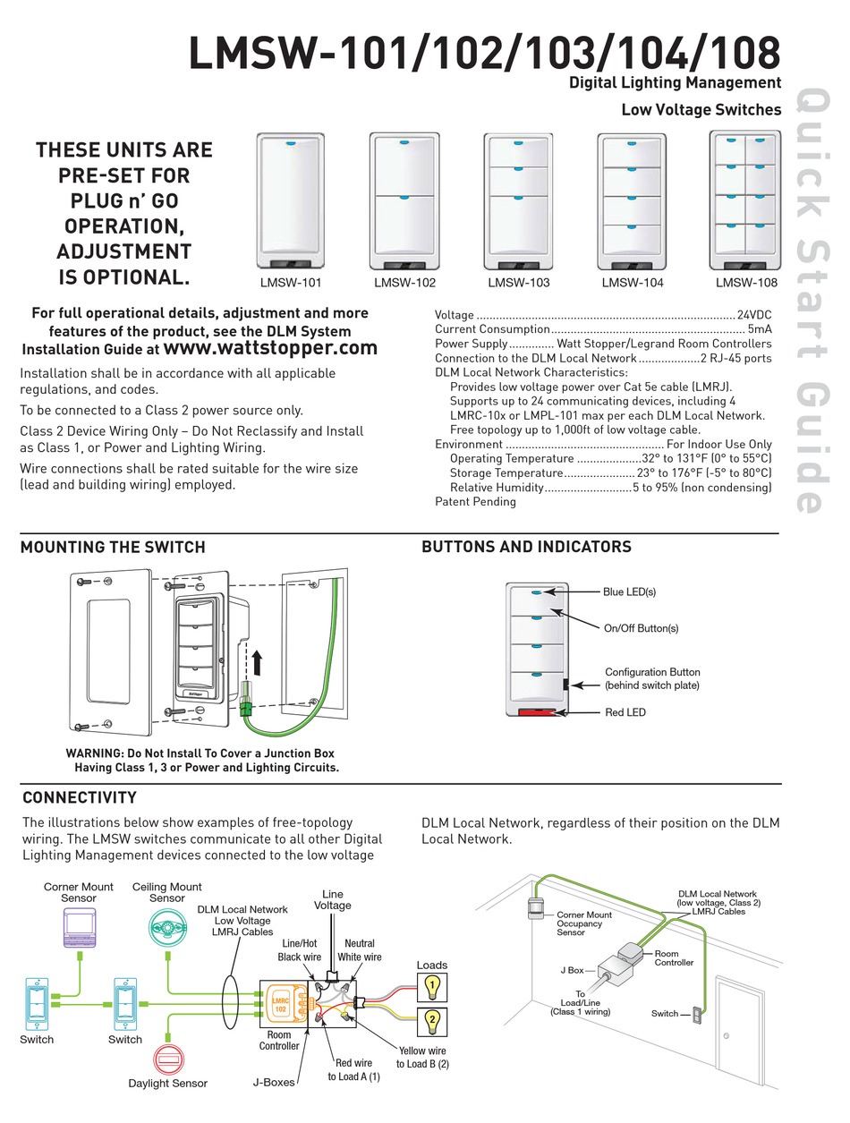
When using more sensors than this multiple power packs are required. Wiring Diagram B LVS 1-Button Latching or Momentary Switch with Pilot LED alia espectiv wners Wiring Diagram D LVS 2-Button Latching or Momentary Switch with Pilot LEDs Wiring Diagram F LVS 3-Button Latching or Momentary Switch with Pilot LEDs Wiring Diagram H LVS 4-Button Latching or Momentary Switch with Pilot LEDs. Page 2 LVSW-101 LVSW-102 LVSW-103 LVSW-104 LVSW-108 Button-Terminal Cross Reference Please 82011 2800 De La Cruz Blvd.
Installation Diagram Manual-On and Bi-Level Switching Load Shed Hold-Off Application Retail Hold-On Application 1 All WattStopper power packs should be installed in accordance with state. Summary of Contents for wattstopper LMRC-101 Page 1 IT MAY DAMAGE COMPUTERS AND OTHER CONNECTED EQUIPMENT. LVSW-100 Series Low Voltage Switches are lighting control devices that use conventional point-to-point low voltage wiring for control of single or multiple loads.
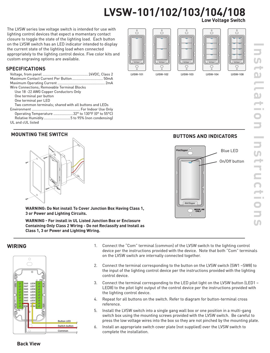
Each button provides a momentary contact that is intended for use with compatible low voltage relay panels or similar lighting control panels or devices. Watt Stopper Wiring Diagram Wiring Schematic Diagram. Wattstopper LVSW-100 Series Low Voltage Switches are lighting control devices that use conventional point-to-point low voltage wiring for control of single or multiple loads.
Black Box PSE518SA Quick Start Manual Quick start manual 4 pages ATEN VS-0404 User Manual Operation users manual 14 pages Antaira LNP-1002C-SFP-T User Manual Operation users manual 24 pages Supermicro SSE-F3548S User Manual Operation users manual 366 pages Lindy 39330 User. Low voltage pushbutton switches for onoff control of one or more loads. Current consumption can be slightly higher when only one sensor per.
LMDM-100 Dimming Wall Switches fit in standard. Make sure power has been turned off at the circuit breaker. WIRING DIRECTIONS Each Wattstopper B347-D power pack can supply power for up to 2 DT-205 sensors.
Sensors are white and use Wattstopper power packs. Wattstopper Hb350w Wet Location Infrared Occupancy Sensor Value. 24 Volt DC Voltage Rating.
After initial wiring is complete check wiring diagram to verify power pack is wired correctly. Connect the LOW VOLTAGE. LMDM-101 Dimming Switch Occupancy Sensor LMRC-212 Dimming Room Controller LMDM-101 Dimming Switch 0-10 Volt Ballast 0-10 Volt Ballast Class 2 0-10 Volt Control Wiring.
Each button on the LVSW switch has an LED indicator intended to display the current state of the lighting load when connected appropriately to the lighting control device. Each Wattstopper BZ series power pack can supply power for 3 DT-205 sensors. 2 Wattstopper 360 Dual Technology Low Voltage Occupancy Sensor version 3 with Light Level Isolated Relay and Manual On feature Double technologie à 360 Détecteur de présence basse.
Legrands Wattstopper product line of Lighting Control Systems and Services is the most comprehensive line of simple scalable and flexible energy-efficient lighting and plug load controls for commercial applications. Order your LVSW-101-I today or contact one of our certified lighting specialists to learn more. INSTALLATION AND WIRING 1.
Order your LVSW-101-W today or contact one of our certified lighting specialists to learn more. Sample Connection Diagram with 0-10 Volt Dimming. Wattstoppers industry-leading energy efficient lighting controls technology and services offering is designed to meet code ensure.
LVSW-101 Low Voltage Switch Input BZ-250 Power Pack must be grounded to. Refer to the wiring diagram on the next page for the following procedures. Connect wires as shown in in the following diagrams depending on application.
Refer to the wiring diagram on the next page for the following procedures. Wattstopper Lmrc 212 347 2 Relay Room Controller 0 10v Dimming. Order decorator style plate separately.
Wattstopper LVSW-100 Series Low Voltage Switches are lighting control devices that use conventional point-to-point low voltage wiring for control of single or multiple loads. Wattstopper Switch LVSW-103 Installation instructions 2 pages. 17 Inch Width X 055 Inch Depth X 41 Inch Height Size.
Lmdc 100 Dual Technology Ceiling Mount Occupancy Sensor. Wattstopper Switch LVSW-102 Installation instructions 2 pages 10. Wiring Mounting Wiring Diagram Mounting Controls Settings Product Controls DIP Switch Settings IW IW IW IW IW 35 FRYHUDJH IW 8OWUDVRQLF.
41 104mm 17 43mm 33mm13. WATTSTOPPER LVSW-101-W Low Voltage Switch 1 button wLED white. LMSW-101 LMSW-102 LMSW-103 LMSW-104 LMSW-108 Connecting LMRJ Cables Loads 1 2 Line Voltage Room Controller J-Box Occupancy Sensor LMSW-102 Switch LMSW-102 Switch Sample Connection Diagram with Multi-way Bi-level Control Plug DLM local network components together in any configuration using Cat 5e cables with RJ45 connectors.
Improper wiring can cause damage to power pack lighting system and occupancy sensor. Connect the low voltage. BLACK wire Return from power pack to Common terminal on the sensor.
Low voltage pushbutton switches for onoff control of one or more loads. MOUNTING THE CONTROLLER ATTACHING CABLES The LMRC-101 room controller can either be mounted external to a junction box placing it in the plenum space or mounted directly inside a 4 x 4 junction box.
Bz 150 Legrand
Wattstopper Lvsw 101 Installation Instructions Pdf Download Manualslib
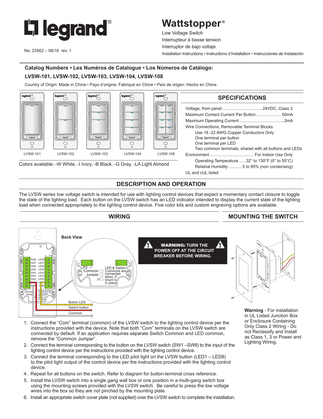
Legrand Lvsw 101 102 103 104 108 Low Voltage Switches Trilingual Lvsw 101 102 103 104 108 Low Voltage Switches Installation Guide Manualzz

Legrand Lvsw 101 102 103 104 108 Low Voltage Switches Trilingual Lvsw 101 102 103 104 108 Low Voltage Switches Installation Guide Manualzz
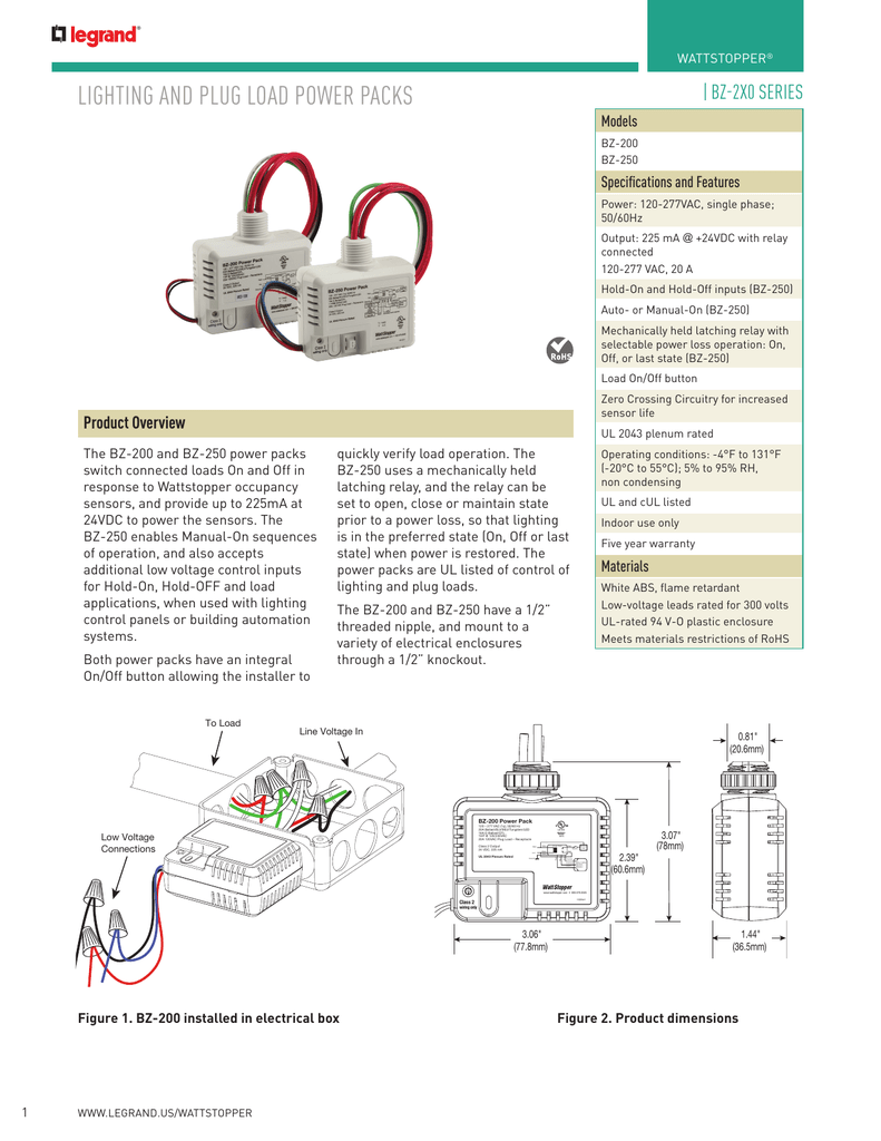
Lighting And Plug Load Power Packs Manualzz
Wattstopper Lmsw 102 Quick Start Manual Pdf Download Manualslib
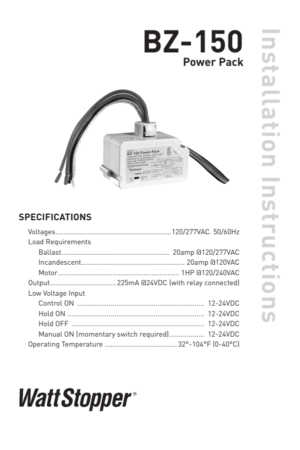
Bz 150 Legrand

Wattstopper How To Wire A Bz 150 Universal Voltage Power Pack Youtube
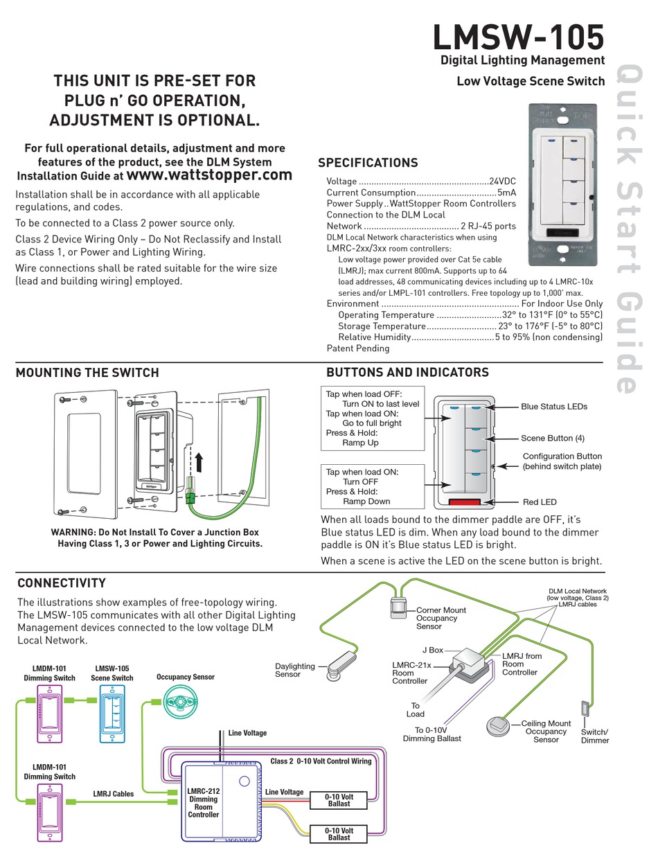
Wattstopper Lmsw 105 Quick Start Manual Pdf Download Manualslib
