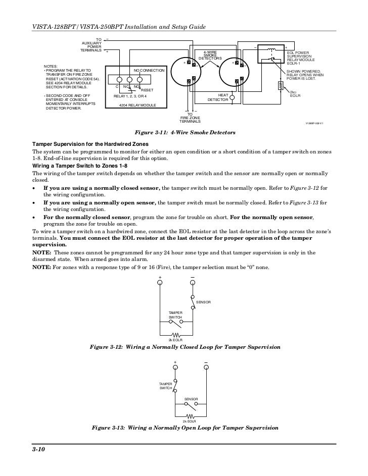
For more details on wiring smoke detectors see. Ademco Vista 128bp Wiring Diagrams Mazda Cx 5 Diagram Audi A3 Yenpancane Jeanjaures37 Fr.
Vista 128bpt Wiring Diagram - If you're searching for picture and video information related to the keyword you have come to pay a visit to the right site. Our site provides you with hints for viewing the highest quality video and image content, hunt and find more enlightening video articles and images that match your interests. includes one of tens of thousands of movie collections from various sources, especially Youtube, so we recommend this movie that you see. This site is for them to visit this website.
Ademco Vista 20p Installation Manual Pdf
The VISTA-128BPVISTA-250BP is an 8-partition UL Listed control panel with the following features.
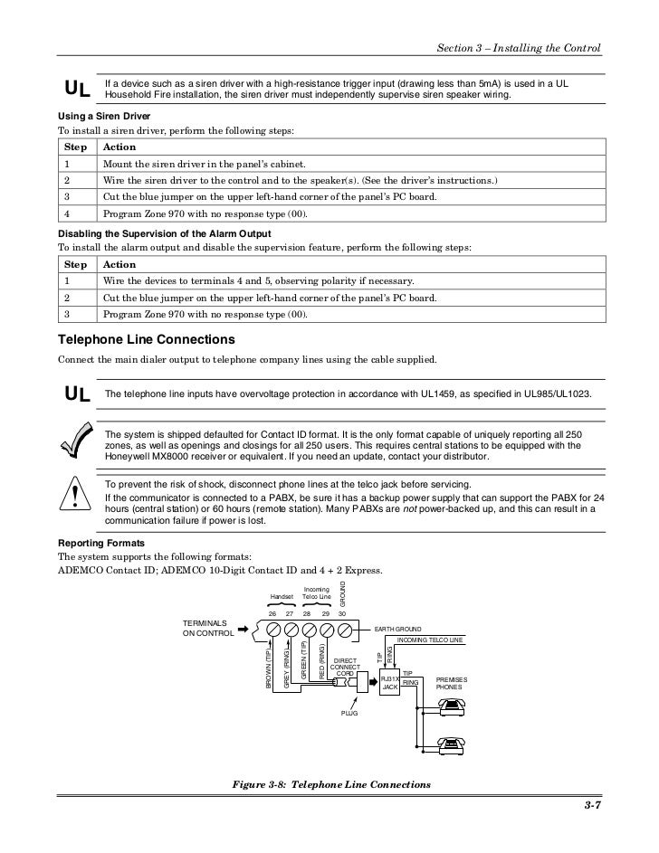
Vista 128bpt wiring diagram. Supports hardwired polling loop and wireless zones Supervision of bells keypads RF receivers. The VISTA-128BPTVISTA-250BPT is an 8-partition UL Listed control panel with the following features. About the VISTA-128BPTVISTA-250BPT All references to the VISTA-128BPT also pertain to the VISTA-128BPTSIA.
This macro will work with the Honeywell Vista Turbo security system. Vista Turbo 128-FBPT Device Type. Or when a short occurs between the Bell and Bell - terminal wiring or between the Bell terminal wiring and earth ground.
Alarm Output Supervision When supervision is enabled the VISTA-128BPTVISTA-250BPT monitors the alarm output wiring for open and short circuit faults while the output is inactive. A diverse line of Resideo initiating devices notification appliances communication devices keypads RF. The system provides a trouble indication Zone 970 when an open occurs.
Smoke Detector Circuit Basics Connecting 2 wire Smoke Detectors Connecting 4 wire Smoke Detectors. Ademco Vista Series 128bp 250bp 128sia. The differences between the two panels are outlined in the SIA CP-01 Quick Reference Chart located at the beginning of this manual.
ONLY APPLIES TO VISTA-128FBPT N 0 remote keypad sounder 1 keyswitch LEDs Must be set to 0 remote keypad sounder. Ademco Vista 128bp Wiring Diagrams Race Car Fuse And Relay Panel Ad6e6 Sehidup Jeanjaures37 Fr. N 0 disable 1 enable Must be set to 1 enable.
About the VISTA-128BPTVISTA-250BPT All references to the VISTA-128BPT also pertain to the VISTA-128BPTSIA. He takes you through the wiring of the transformer keypad. Zones 3 through 8 share their Lo sides in pairs.
Remote Keypad Sounder Wiring 44 Figure 3-23. Product Specifi cations. Vista128bpt Wiring Diagram 28112018 28112018 5 Comments on Vista128bpt Wiring Diagram View and Download Honeywell VISTABPT installation and setup manual in the SIA CP Quick Reference Chart located at the beginning of this manual.
The differences between the two panels are outlined in the SIA CP-01 Quick Reference Chart located at the beginning of this manual. The following is a step-by-step procedure recommended for programming your VISTA-128BPVISTA-250BPVISTA-128SIA systems. 350ZONE TYPES 16-18 REST.
Uses same wiring connection as Honeywell 5800 series receivers. They only provide general information and cannot be used to repair or examine a circuit. When programming these zones in the Vista-128BPT choose a 24 Hour zone type such as 24 Hour Audible ZT 07 24 Hour Silent ZT 06 or 24 Hour Auxiliary ZT 08.
Jon Boroughs of AlarmSystemStoreCom shows you the basic wiring on a Honeywell Vista alarm system. Vista 128bp V1 Installation Manual. VISTA-128BPE VISTA-128BPT VISTA-128FBP-9 VISTA-128FBPT VISTA-250BPE VISTA-250BPT VISTA-250FBP-9 VISTA-250FBPT.
To program the VISTA-128SIA you must use the supplement in conjunction with this manual. Vista 128bpt And 4202 Relay Wiring Diagram. In the Normally Open circuit the 2K End of Line Resistor connects across the two terminals at the last panic switch wired in the circuit.
Honeywell Vista Turbo 128 -BPT Arm v1 2. This fire and burglary control panel supports up to eight partitions and up to 128 zonespoints using hardwired wireless and V-Plex addressable technologies. Wiring the VistaKey 48 Figure 3-25.
This module provides control of the armdisarm functions for all user IDs and user codes. 355RESET ON 2ND OFF FOR BELL 1 N 0 disable 1 enable Must be set to 0 disable. VISTA panel Wiring Diagram.
The new VISTA-128FBPT provides the ultimate protection for life and property. This is called Parallel wiring. K0376v2 Vista 250fbp V4 Installation Manual.
Remote Keyswitch Wiring 44 Figure 3-22. Ademco Vista 128bp Wiring Diagrams show the circuit flow with its impression rather than a genuine representation. Zones 2-8 Standard Burglary Zones Looking at the wiring diagram zones 1 2 each have dedicated terminals for the Hi and Lo - sides of their loops.
321MAX ATEMPTS Y 1-8 Must be set at 3 4 or 5. All items labeled SIA Guidelines in the manual pertain to the VISTA-128BP and VISTA-250BP only. Connecting the Backup Batteries 56 VISTA-128FBPT VISTA-250FBPT Summary of Connections Diagram Inside Back Cover.
The VISTA-128BPTVISTA-250BPT is an 8-partition UL Listed control panel with the following features. DS1034A - EN7290 Datasheetindd. Structured Wire Enclosure To Sensors 6100ICM Vista-ICM Security Panel Security Keypad HeatingCooling Keypad Bus Touch Panel 182 AWG 100 Max 120VAC Power Supply RFPLC Lighting LIGHT-ICM RS232 Network HUB Ethernet Network Power Supply 165 VAC Power Supply In2 TPW8 Vista Panel T8635L 1013 T8635L 1013 T8635L 1013 W8735A 1005 Vista 15 Vista 20 Vista 128 Vista.
VISTA-128-FBP-T-HONEYWELL - Hybrid Fire and Burglary Alarm Panel Enclosure Power Supply and PC Board Up to 128 Wired or Wireless Zones 120 V-Plex Zones 8 Partitions Works With AlarmNet and Total Connect. Wiring Communicator to Keypad Terminals 46 Figure 3-24.
Honeywell Vista 128bpt Connections Summary
Vista 128fbp Manual Espanol
Vista 128 Programming Manual
Install Guide Honeywell Vista 128bpt And 250bpt
Honeywell Gsmv4g Posts Alarm Grid
How Do I Connect A 4193sn To A Vista 128bpt 250bpt Or Vista 50 Alarm Grid
0oijknor8v36rm
Ademco Vista 128b 128bp Wiring
Honeywell Fire Alarm System Wiring Diagram Pdf


