Please note that the stale air never mixes with the fresh air. When cutting or drilling into a wall or ceiling do not damage electrical wiring and other hidden utilities.
Venmar Wiring Diagram - If you're looking for video and picture information related to the keyword you have come to pay a visit to the ideal blog. Our website gives you suggestions for viewing the highest quality video and image content, hunt and find more informative video articles and graphics that match your interests. comprises one of thousands of video collections from several sources, especially Youtube, so we recommend this video for you to view. This blog is for them to visit this site.
20 40 60 Minutes Timer Switch
The following diagram shows the terminal strip in the control box.

Venmar wiring diagram. E15 ECM HRV 90H-V ECM HRV E15 ECM ERV E15 HRV 90H-V 90H-V ECM ERV E10 HRV 60H-V. These products earned the ENERGY STARby meeting strict energy efficiency guidelines set by Natural Resources Canada and the US EPA. Soak the heat recovery core for 3 hours in a solution of luke- warm water and mild soap.
There are 2 methods for connecting the unit to the furnaceair handler. Installation work and electrical wiring must be done by a qualified persons in accordance with all applicable codes and. WARNING Stale air from building Fresh air.
No Description Venmar Venmar vänEE vänEE 18 HE 26 HE 2000 HE 3000 HE 1 Simple Collar 8 01657 01657 01657 01657 2 Double Collar 6 00865 00865 00865 00865 3 Filter 14875 x 14375 x. The unused wire needs to be protected with some kind of connector to prevent it from giving you a shock. Visit our website at wwwvenmarca or wwwvaneeca.
The power supply cord has a 3-prong grounding plug for your personal safety. To access the Venmar units. VENMAR AVS ERV EKO 15 HRV EKO 15 CONSTRUCTO 15V vänEE ERV 90H-V ECM HRV 90H-V ECM 90H-V.
You have a choice of any two of high medium or low speed. X24 HRV ECM X30 HRV ECM X24 HRV ECM-N X30 HRV ECM-N G2400H ECM G3000H ECM X24 ERV ECM X30 ERV ECM X24 ERV ECM-N X30 ERV ECM-N G2400E ECM G3000E ECM. Please see Documents folder.
Current Wiring Venmar Main Wall Control 40350 G R Y on Control to G R B on Terminal Venmar 20 Minute Push Button 12030 I OC OL on Control to I OC OL on Terminal Sugessted Wiring Venmar Main Wall Control 40350 G B on Control to G B on Terminal Venmar 20 Minute Push Button 12030 I OC OL on Control to I OC OL on Terminal. OPTIONAL CONTROLS A three-wire connection allows up to ten five for Constructo lighted push-button. Refer to wiring diagram wired.
Connect this opening to the Fresh air to building port of the HRVERV use steel duct see figure beside. Hrv Wiring Diagram Electrical Manual Changeover Switch Wiring Diagram For Portable Generator Manual changeover switch are mostly. This unit must be grounded.
Each end branch will have to transport a 70 cfm air flow 140 divided by 2. INSTALLATION 21 LOCATING AND MOUNTING THE UNIT The wearing of safety glasses and gloves is recommended when installing maintaining or cleaning the unit to reduce the risk of injury that could be caused by the presence of thin metal andor high moving parts. There are more wires on the motor than you will be using.
20-Minute Push Button Part No. Rinse thoroughly and let dry completely 5. No Description Venmar Venmar vänEE vänEE 18 HE 26 HE 2000 HE 3000 HE 1 Simple Collar 8 01657 01657 01657 01657 2 Double Collar 6 00865 00865 00865 00865 3 Filter 14875 x 14375 x 074 04771 04771 04771 04771 4 Damper Actuator 6 W 01295 01295 01295 01295 5 Damper Actuator Rod 7250 10905 10905 10905 10905.
Table on page 5 indicates for a 5 Ø duct. A heat recovery ventilator HRV was part of the home package we and field- tested tricks that you wont find in any manufacturers manualVENMAR KUBIX HRV PART NO. Let it soak for 3 hours in a mixture of warm water and mild soap dishwashing liquid.
295 kg port diameter 6 152 mm 6 152 mm drain diameter 12 12 mm 12 12 mm installation chains and springs provided with the unit motor speed high and low speed factory set optional increased low speed electrical supply 120 v 60 hz 120 v 60 hz power consumption 160 w atts 195. They meet ENERGY STAR requirements only when used in Canada. 295 kg 65 lb.
31 Diagrams of Air Flows 8 VF0010 VF0003 during. I chose high and low. In this section you will find installation manuals technical data sheets and product brochures for Venmar products.
There is a color code diagram printed on the motor label. Clean the recovery core as follows according to the type of unit. The Venmar and vänEE performance charts are listed on the specification sheets of these units.
The high speed air flow of 70 cfm is close enough to the recommended value 75 and far. It must be plugged into a. Supply side connection Cut an opening into the furnace supply duct at least 18 inches 05 m from the furnaceair handler.
The direction of the air flow is indicated in each of the following diagrams Figures 1 and 2. Venmar CONSTRUCTO Wall Control Y R G B Typical Wiring Schematic Side View of Constructo 15 or 20 Constructo Wall Control Rear View of Lighted Push Button OL OC I Toggle Switch B G R OL OC I Low Speed RemoteOff High Sp ed Dehumidistat Dial SS071500-PC1000 Shelter Supply Inc. The direction of the air flow is indicated in each of the following diagrams see Figures below.
Clean the recovery core as follows. Wash both core filters under lukewarm water with mild soap. Air exchangers kitchen hoods.
Do not use this unit with any solid-state speed control device other than those specified in section 72. The wall control is surface mounted - no wiring box is required. Technical data contd15 specifications model 100h 200h weight 65 lb.
Venmar 20-Minute Lighted Push Button 3-wire VanEE equivalent. The Venmar supports two speeds. All the Venmar main controls are connected using a 4 conductors cable telephone cable.

Installation Guide Vanee Venmar Avs Erv Eko 1 5 Erv 90h V Ecm Hrv Eko 1 5 Hrv 90h V Ecm Constructo 1 5v 90h V Pdf Free Download

Installation Guide Vanee Venmar Avs Erv Eko 1 5 Erv 90h V Ecm Hrv Eko 1 5 Hrv 90h V Ecm Constructo 1 5v 90h V Pdf Free Download

Installation Guide Vanee Venmar Avs Erv Eko 1 5 Erv 90h V Ecm Hrv Eko 1 5 Hrv 90h V Ecm Constructo 1 5v 90h V Pdf Free Download
Wiring Help

Venmar Constructo 2 0es Hrv Gasexperts

Installation Guide Vanee Venmar Avs Erv Eko 1 5 Erv 90h V Ecm Hrv Eko 1 5 Hrv 90h V Ecm Constructo 1 5v 90h V Pdf Free Download
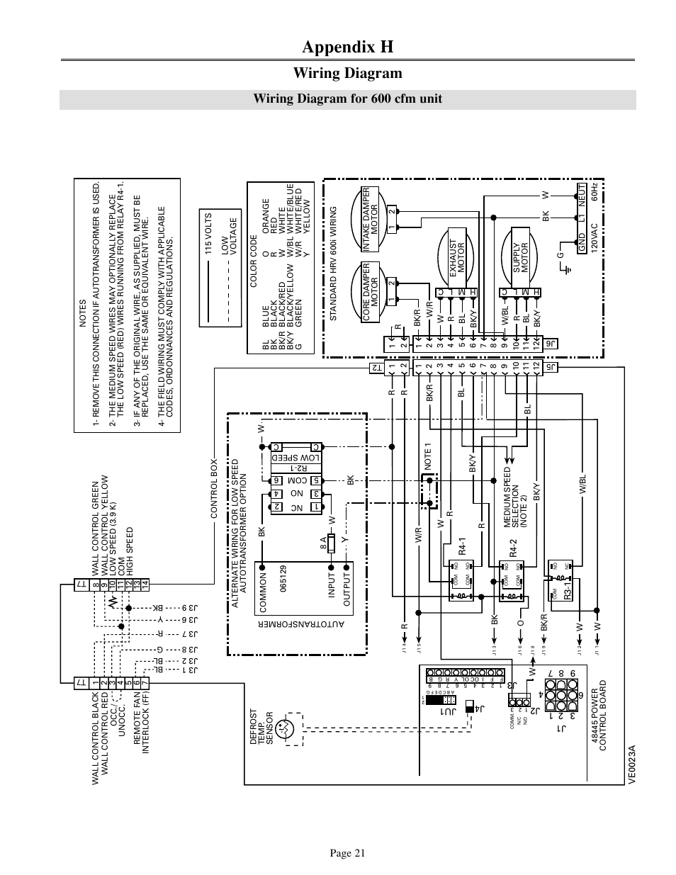
Appendix H Wiring Diagram Wiring Diagram For 600 Cfm Unit Venmar 700 Cfm User Manual Page 21 24
Wiring Help With Nest Vanee Air Exchanger
Ecobee3 Wiring Diagrams Ecobee Support
