If there is an earth fault between the CTs. Rated Current Plug seng Range.
Restricted Earth Fault Relay Wiring Diagram - If you're looking for picture and video information related to the keyword you have come to pay a visit to the right blog. Our site gives you hints for seeing the highest quality video and image content, search and locate more enlightening video content and graphics that match your interests. includes one of thousands of video collections from various sources, especially Youtube, therefore we recommend this movie for you to view. This site is for them to stop by this website.
![]()
Restricted Earth Fault Protection System Explanation Working Circuit Globe
The protection relay can be parameterized for use with threephase and.

Restricted earth fault relay wiring diagram. The earth fault protection scheme consists the earth fault relay which gives the tripping command to the circuit breaker and hence restricted the fault current. Wiring Diagram for the MD32G Rotating Machine Differential Relay used for 87G and 51N Protection www 5. The relays used in power system protection are of different types.
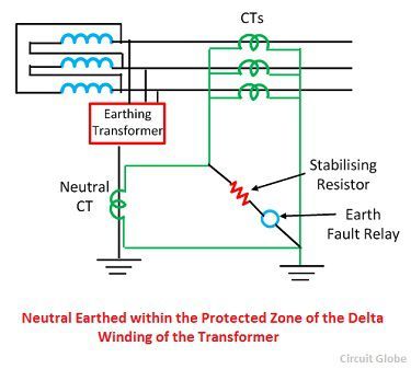
Restricted Earth Fault Operation Under normal conditions and by application of Kirchhoffs laws the sum of currents in both current transformers CTs equals zero. In Restricted Earth Fault scheme the common terminals of phase CTs are connected to the secondary of Neutral CT in such a manner that secondary unbalance current of phase CTs and the secondary current of Neutral CT will oppose each other. If the transformer is connected deltastar as shown in Figure 6 balanced three-phase through current suffers a phase change of 30.
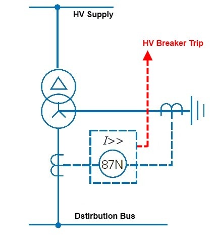
Restricted Earth Fault REF Protection Apply the REF protection feature to provide sensitive detection of internal ground faults on grounded wye-connected transformer windings and autotransformers. High impedance restricted earth fault relays can be used to detect earth faults on transformer windings reactor windings or the stator windings of machines. Wiring Diagram Of Earth Fault Relay Full Hd Version Lamm Experts It Unrestricted Earth Fault Protection Working Priciple Electrical4u Connections Of Overcur Relay Part 2.
The 5B3 relay uses a low pass filter circuit to achieve this. Contacts SR OR HR 2 NO SR. Relay model no.
05 to 2 amps. The earth fault relay is placed in the residual part of the current transformers shown in the figure below. If these both currents are equal in amplitude there will not be any resultant current circulates through the said closed path.
Correct operation of transformer differential protection requires that the transformer primary and secondary currents as measured by the relay are in phase. It finally mis-operated on feeder single-phase switching which looked like an in-zone ground fault to the relay. For busbar protection it is considered good practice by.
The recommended relay current setting for restricted earth fault protection is usually determined by the minimum fault current available for operation of the relay and whenever possible it should not be greater than 30 of the minimum fault level. . Earth leakage relay and earth fault relays are used to sense earth faults.
RESTRICTED EARTH FAULT RELAY REFR opens a new chapter for power system protective relaying. The connection of earth fault. 2008 Company ISO 9001-2008.
Client has requested us to wire based on the wiring diagram below. Current setting 02 to 08 amps. The illustration shows the principal of REF protection.
50 Hz Auxiliary supply. The digital processing of measured values and the ability to perform complex. INSTHIGH STAB CIRCULATING CURRENT RELAY.
Earth fault is an undesirable condition at which current flow from a conductor to earth. Order the SEL-787 with the Slot E card containing the 1 A or 5 A current input for REF protection. Restricted Earth Fault Protection is also known as differentia.
This can happen when a current-carrying conductor falls on the ground or the body of any equipment or when someone touches a live conductor with adequate PPE or due to insulation failures. But i have some doubts on their wiring diagram. RESTRICTED EARTH FAULT RELAY inside faults.
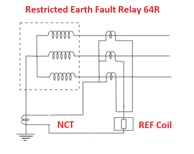
MD32GL5JS is an MD32G. This relay protects the delta or unearthed star winding of the power transformer against the fault current. Restricted Earth Fault Relay 5B3 For some restricted earth fault applications the primary fault setting needs to be greater at harmonic frequencies than the setting at the fundamental frequency.
The earth fault can be dispersed by using the restricted earth fault protection scheme. Figure 1 Internal and external circuit diagram for unbiased differential protection of generatorsreactors and synchronous motors using type MCAG 34 relay Figure 2 Type MCAG14 relays applied to restricted earth fault protection of power transformer Simple reliable and secure unit protection. Relay Model No CAG14AF14A.
Case size 1D V 10T. 5 80 in steps of 1 Operang Time. The three-line diagram and single-line diagrams for the project corroborated and showed the correct CT neutral polarity towards ground but in the field it was the opposite and the commissioning guys missed it.
I have an application whereby the client is requesting for Restricted Earth Fault protection and standby earth fault protection for transformer. In this video the philosophy behind the restricted Earth Fault Protection has been elaborated. 85275V ACDC Output Relay Operang Temperature.
Typical transformer restricted earth fault protection arrangements are shown in section 21. Of 3981 overcur relay cdg type diagram electrical fire prevention restricted earth fault protection system explanation working ground fault protection relays littelfuse. Relay type CAG 14.
33 Phase Correction. No adverse reduction in fault setting can occur with the high frequency current which may be. The windings of many medium and small sized transformers are protected by restricted earth fault REF systems.
Restricted Earth Fault Protection System Explanation Working Circuit Globe
Restricted Earth Fault Protection
Restricted Earth Fault Protection 64r Working Transformer Electrical4u

Question On How To Connect Relay For Restricted Earth Fault Protection For 4 Wire System Wye Transformer Cr4 Discussion Thread
![]()
Restricted Earth Fault Protection Of Transformer Ref Protection Electrical4u
Restricted Earth Fault Protection Of Transformer Ref Protection Electrical4u
High Impedance Protection Ct Connection For 5 Ct Arrangement Download Scientific Diagram

Restricted Earth Fault Protection In Dyn Transformers By Abhijeet Limaaye Linkedin

What Is Restricted Earth Fault Relay 5 Ct Explanation Youtube
