Each button has an LED indicator that can serve as a status indicator or as a. Input Voltage Output BallastELV MLV IncanLED E-Ballast CFL Motor Plug Load BZ-250 120-277VAC single phase.
Legrand Lvsw 101 Wiring Diagram - If you're looking for picture and video information related to the key word you've come to visit the ideal blog. Our site provides you with suggestions for seeing the highest quality video and image content, hunt and locate more enlightening video articles and graphics that match your interests. includes one of tens of thousands of video collections from several sources, especially Youtube, so we recommend this video that you see. It is also possible to contribute to supporting this site by sharing videos and images that you like on this blog on your social media accounts like Facebook and Instagram or educate your closest friends share your experiences about the ease of access to downloads and the information you get on this site. This site is for them to stop by this site.
Wattstopper Lmdm 101 Programming
Current Rating 30 Milliamp Per LED UPC.
Legrand lvsw 101 wiring diagram. The Wattstopper product line offers the most comprehensive line of simple scalable and flexible energy efficient lighting controls and solutions for commercial applications. LMDM-100 Dimming Wall Switches fit in standard. Wattstopper Switch LVSW-101 Installation instructions 2 pages 9.
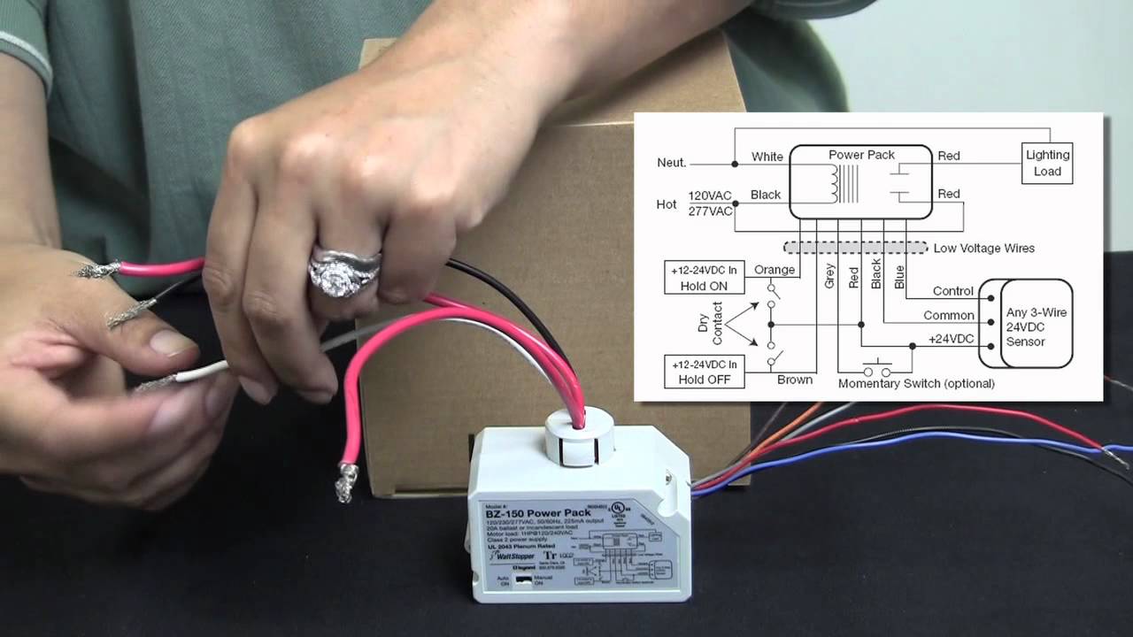
Wire Multi-button Switch LVSW-101 Do not use pilot or locator light connections Red 24VDC Grey Manual ON Sx Com. To add a MANUAL SWITCH such as the LVSW Momentary Toggle Switch or RS2-3 Low Voltage Momentary Switch to the above applications see wiring diagram Manual-On wiring with low voltage momentary switch connect. Wattstopper Switch LVSW-103 Installation instructions 2 pages.
41 104mm 17. Wattstoppers networked lighting control solution Digital Lighting Management offers the flexibility in design for wired or wireless networking while allowing for energy savings. After initial wiring is complete check wiring diagram to verify power pack is wired correctly.
The Manual ON function is facilitated by installing a momentary switch such as Wattstopper LVSW Momentary Toggle. Two-wire Switch Three-wire Switch Multibutton Switch Do not use pilot or locator light connections Power Packs Catalog No. Wire from one side of switch to 24V terminal on.
Wire from one side of switch to 24V terminal on sensor. Wattstoppers industry-leading energy efficient lighting controls technology and services offering is designed to meet code. Energy-Saving Digital Lighting Controls for Commercial Spaces.
Our brands products resources and pages are group into divisions. WATTSTOPPER LVSW-101-W Low Voltage Switch 1 button wLED white. LMSW-101 LMSW-102 LMSW-103 LMSW-104 LMSW-108 Connecting LMRJ Cables Loads 1 2 Line Voltage Room Controller J-Box Occupancy Sensor LMSW-102 Switch LMSW-102 Switch Sample Connection Diagram with Multi-way Bi-level Control Plug DLM local network components together in any configuration using Cat 5e cables with RJ45 connectors.
Digital lighting Managments active Dim feature gives designers the option of reducing wall clutter by facilitating scene setting without the need for individual dimming switches for each load. Switches do not include face plates. 17 Inch Width X 055 Inch Depth X 41 Inch Height Size.
Click Add to Cart to buy Wattstopper LMSW-103-W Digital Switch 3-Button. 24 Volt DC Voltage Rating. Lighting Lighting Controls Lighting Control Systems - Wired Room Controllers.
To add a MANUAL SWITCH such as the LVSW Momentary Toggle Switch or LISTED RS2-3 Low Voltage Momentary Switch to the above applications see wiring diagram Manual-On wiring with low voltage momentary switch connect. Choose from one of Legrands brands. Filter and find a product resource or page you are looking for based on a.
For help with Digital Switch 3-Button Infrared White from Wattstopper. Wattstopper Switch LVSW-102 Installation instructions 2 pages 10. 8008798585 Recycle Santa Clara CA 95050 www.
Lighting controls and systems from Wattstopper make complex functionality simple and crate the. The lMSW-105 Digital Scene Switch is a low. User Manuals Guides and Specifications for your wattstopper LMSW-103 Switch.
BLUE wire from power pack to Control Out terminal on sensor. Wattstopper LMSW-103 Manuals User Guides. LVSW-101 Low Voltage Switch Input COM SW1 LVSW-101 Low Voltage Switch Input BZ-250 Power Pack must be grounded to ensure signal integrity not for safety ground.
Refer to the wiring diagram on the next page for the following procedures. Order decorator style. We would like to show you a description here but the site wont allow us.
5060Hz 16A 16A 14HP 15A. Connect the LOW VOLTAGE. LVSW-101 Low Voltage Switch Input BZ-250 Power Pack.
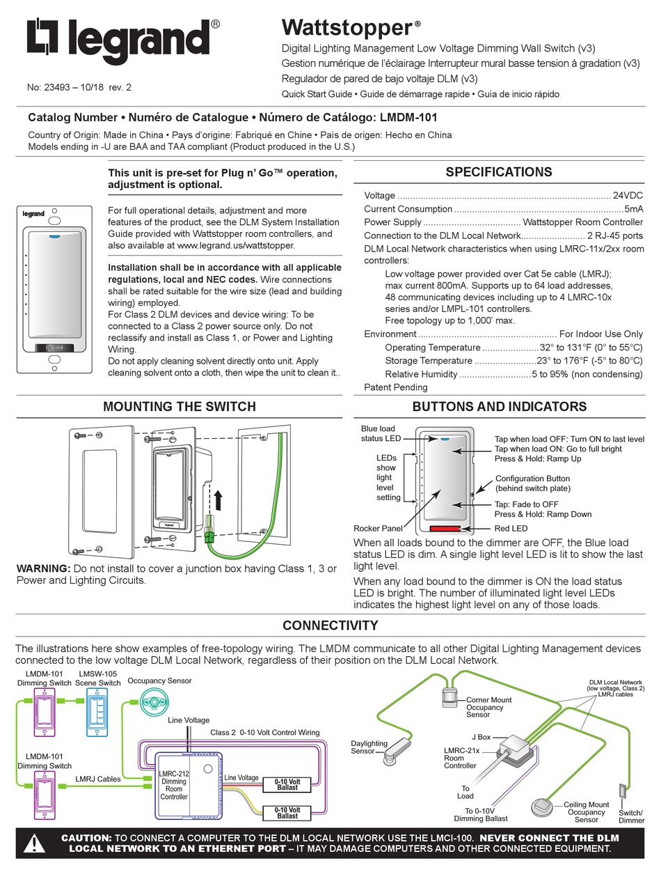
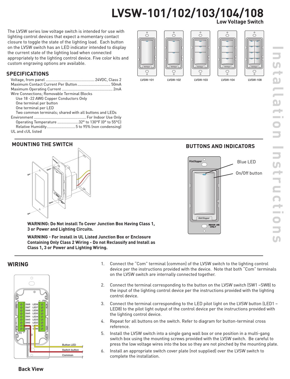
Each button provides a momentary contact that is intended for use with compatible low voltage relay panels or similar lighting control panels or devices. Ground Ground Fixture A Fixture B A B Sensor CeilingWall 24VDC Any To Additional Sensors Auto ON Man ON Auto ON Man ON Low Voltage Wires Low Voltage Wires Notes 1. LMDM-101 Digital Dimming Wall Switches to create a flexible and elegant small dimming system.
Each button on the LVSW switch has an LED indicator intended to display the current state of the lighting load when connected appropriately to the lighting control device. RED wire 24VDC from power pack to the red wire on the sensor. Database contains 1 wattstopper LMSW-103 Manuals available for free online viewing or downloading in PDF.
LVSW-101 Low Voltage Switch Input Optional Neutral Line 120VAC 277VAC Auto ON Man ON. LMDM-101 Dimming Switch Occupancy Sensor LMRC-212 Dimming Room Controller LMDM-101 Dimming Switch 0-10 Volt Ballast 0-10 Volt Ballast Class 2 0-10 Volt Control Wiring. Filter for different types of resources like CAD drawings BIM objects guide form specs online configurators white papers brochures or product cut sheets.
Quick start manual. Legrands Wattstopper product line of Lighting Control Systems and Services is the most comprehensive line of simple scalable and flexible energy-efficient lighting and plug load controls for commercial applications. Improper wiring can cause.
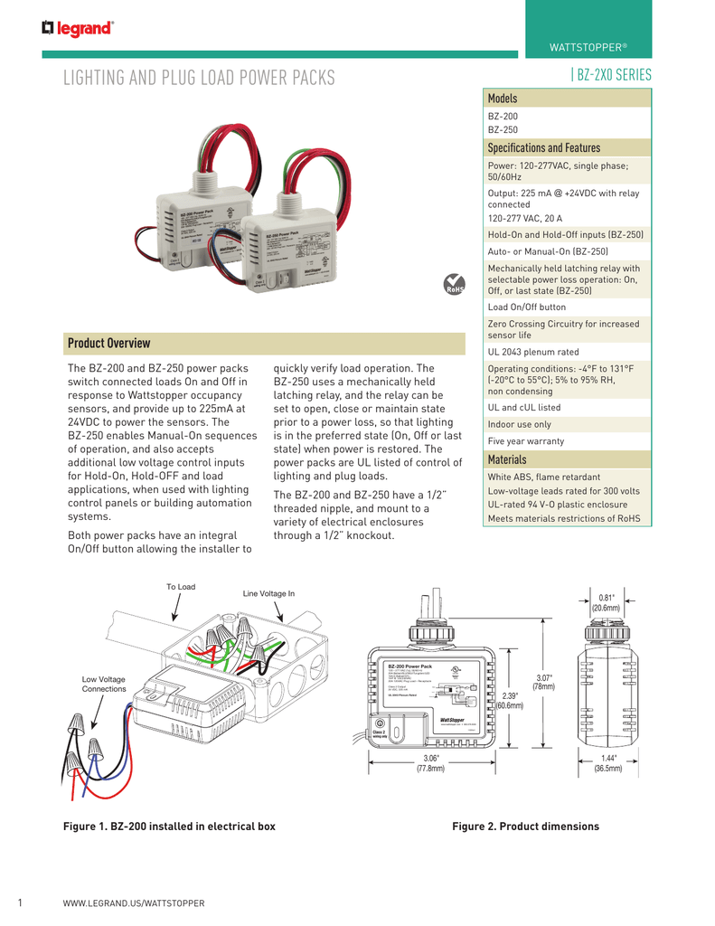
Create scalability with the interoperability to integrate with existing systems of record via BACnet. 5060Hz 24VDC 225mA 20A 16A 1HP 20A BZ-250-U BZ-250-347 120-347VAC single phase. Page 2 LVSW-101 LVSW-102 LVSW-103 LVSW-104 LVSW-108 Button-Terminal Cross Reference Please 82011 2800 De La Cruz Blvd.
BLUE wire from power pack to Control Out terminal on sensor. Sample Connection Diagram with 0-10 Volt Dimming. LVSW-100 Series Low Voltage Switches are lighting control devices that use conventional point-to-point low voltage wiring for control of single or multiple loads.
Bz 150 Legrand

Legrand Lvsw 101 102 103 104 108 Low Voltage Switches Trilingual Lvsw 101 102 103 104 108 Low Voltage Switches Installation Guide Manualzz
Bz 150 Legrand
Lighting And Plug Load Power Packs Manualzz
Wattstopper Lvsw 101 Installation Instructions Pdf Download Manualslib
Wattstopper How To Wiring A Bz 150 Universal Voltage Power Pack Youtube
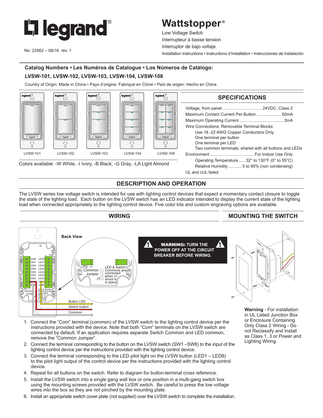
Legrand Lvsw 101 102 103 104 108 Low Voltage Switches Trilingual Lvsw 101 102 103 104 108 Low Voltage Switches Installation Guide Manualzz

Wattstopper Lvsw 101 I 1 Button Low Voltage Wall Switch 24v Ivory Prolighting
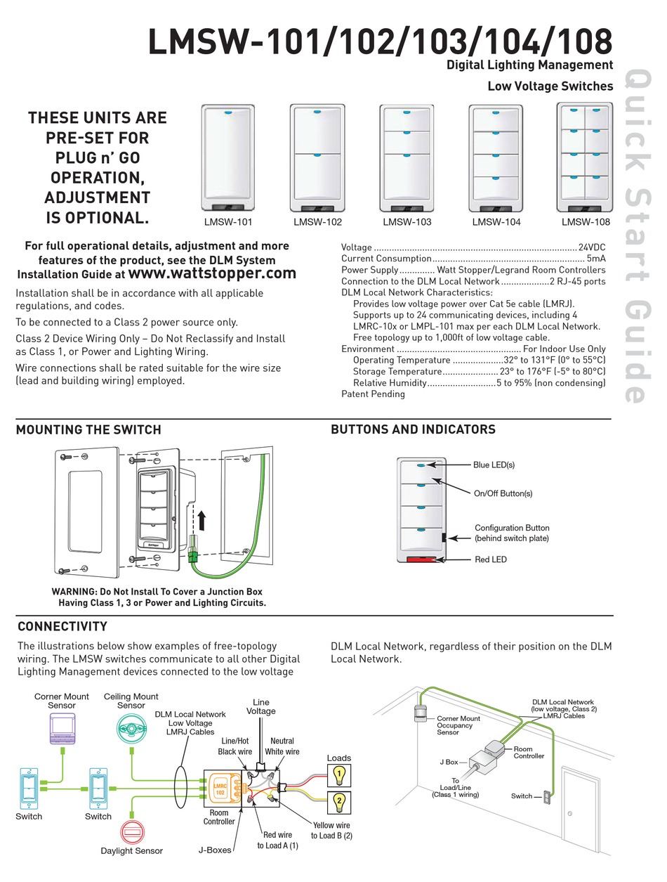
Wattstopper Lmsw 102 Quick Start Manual Pdf Download Manualslib
