Start the vehicle with the key You shouldnt have to change any mode options for your vehicle. Release the button when the LED flashes.
Xk01 Wiring Diagram - If you're looking for picture and video information linked to the key word you've come to visit the ideal site. Our website gives you suggestions for seeing the highest quality video and image content, hunt and locate more informative video content and images that match your interests. comprises one of thousands of movie collections from various sources, especially Youtube, therefore we recommend this video for you to view. It is also possible to bring about supporting this site by sharing videos and graphics that you like on this blog on your social media accounts such as Facebook and Instagram or educate your closest friends share your experiences about the simplicity of access to downloads and the information that you get on this website. This site is for them to stop by this website.
Xk01 Gmdl5x En Ig Vm20071129 Cdr Manualzz
The KILRV Sold Seperately must be used if the vehicle will only.
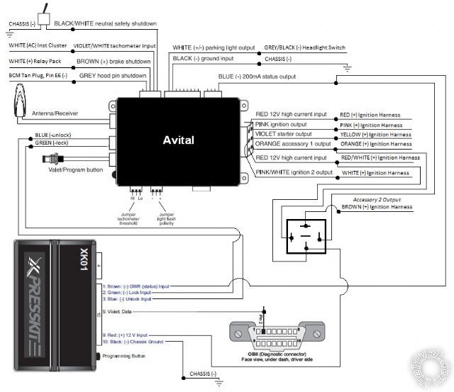
Xk01 wiring diagram. Integrated Security Monitoring. Xpress kits all those you can install it yourself use google alot in wiring diagrams and how to upgrade the firmware so it will work. Door pin status output - Driver.
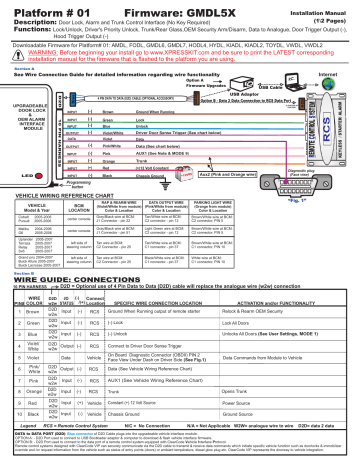
All three installation types provide a GM immobilizer data override and door lock alarm and trunk control interface. Primary interface control functions include. Aux2 PinkWhite Wire Input.
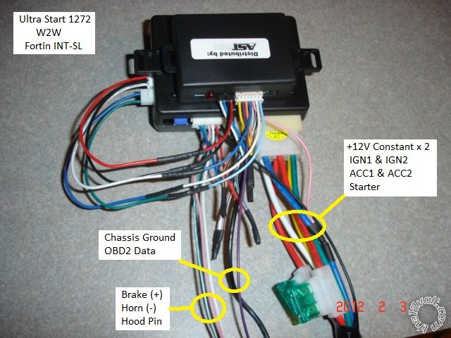
I just bought a viper 5901 remote starterkeyless entry. Wiring Diagram W06 - Wiring Harness for Gear Shift Lever Switches from Serial Number 920066 Wiring Diagram W07 - H4 Farm Headlight Wiring Harness from Serial Number 920066. The XK09 comes pre-loaded with the most comprehensive GM solution on the market and also features the all in one Chrysler door lock and override data solution for almost all ChryslerDodge models.
Unplug the 10 pin harness hold the programming button in and plug the harness back in. What they do is they give you a hint. Complete All Inclusive Technical Manual with electrical wiring diagrams for John Deere Tractors 5215F 5315F 5515F 5615F 5215V 5315V 5515V 5615V with all the workshop information to maintain diagnostic repair rebuild like professional mechanics Diagnose Operation Tests Repair Service Troubleshooting.
Limited One-Year Consumer Warranty. 1003 PR_SU 1000 2202012. Does anybody know how to wire it or possibly send me a link to a wiring diagram.
Page 19 DLPK CANBUS DOORLOCK AND IMMOBILIZER INTERFACE RFLOOP may be required WIRING SCHEMATIC CONFIGURATION SCHÉMA DE BRANCHEMENT Configuration 15 Configuration 24 Volvo Push-to-Start. Door locks trunkhatch release factory alarm door pin status output - driver passenger sliding door control window roll-up. Aux1 Pink Wire Negative OPTION 2 1st Pulse Unlock Driver Door 2nd Pulse Unlock All Doors.
Also the remote starter is d2d compatable. Related Manuals for Xpresskit XK09. Data-to-Data D2D only DL.
Transponder Immobilizer Override SS. Door locks Trunkhatch release Factory alarm Door pin status output - Driver passenger sliding door control Window roll-up GM Passlock II GM. Upgradeable Multi Vehicle Interface Solution XK01 programmable door lock alarm control interface is preloaded with upgradeable firmware AMDL compatible with select GM Chrysler Dodge Jeep vehicles Primary interface control functions include.
NA OPTION 1 1st Pulse Unlock All Doors. But yes the XK01 puts out data signals on the purple wire that command the car to lock unlock and turn off the Passlock II anti-theft system so the remote starter can turn on. See the Vehicle Application Guide on page 2 for more information.
XK09 is a blend of multiple XK modules in one it covers all of the same vehicle as the XK01 XK06 and XK The XK09 comes pre-loaded with the most comprehensive GM solution on the market. Xpresskit XK09 Installation Manual 12 pages. XK01-GMDL6X is an OE door lock and alarm control interface for select Buick Cadillac Chevrolet GMC Hummer Pontiac Saturn and Suzuki vehicles.
The available functions include. Aux2 PinkWhite Wire Positive. XK01 programmable door lock alarm control interface is preloaded with upgradeable firmware AMDL compatible with select GM Chrysler Dodge Jeep vehicles.
John Deere 5215FV 5315FV. We know its difficult to keep track of your guides so download any of your AstroStart Owners Guides here. 20120511 Installation Type A Wiring diagram for types 1 to 4.
Primary interface control functions include. Should i use d2d and just run the wires i need to make it workbiggun. XK015-Pin Connector for Starter Relay K01 XK025-Pin Connector for Hi-Lo Relay ON XK035-Pin Connector for Hi-Lo Relay OFF.
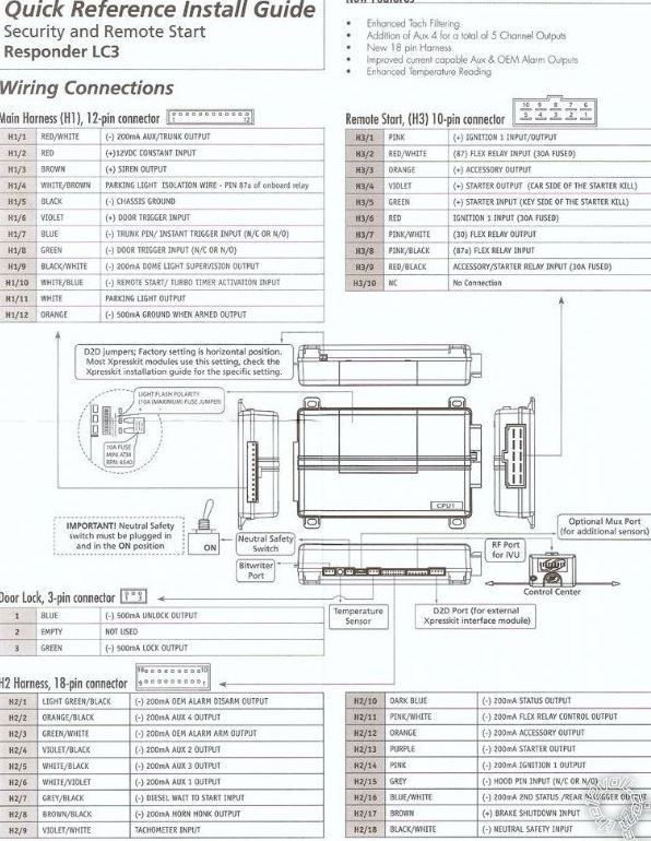
Also See for Xpresskit XK09. Ypes 1 2 use a Single-Wire CAN while type 3 uses a J1850 wire. Wiring diagram Control Button Valet Switch Door Lockunlock Harness Side View Antenna Antenna LED Programming indicator Parking light jumpers Primary Harness Remote Start Harness Heavy Gauge Relay Side View Satellite Harness Red 4-pin port Bitwriter ESP2 or D2D 4x03 Wiring connections Main Harness H1 9-pin connector H11 LIGHT GREEN BLACK.
Xpresskit XK09 SoleX Series Installation Manual 21 pages. Email Our Support Team. Aux2 PinkWhite Wire Output.
Pushbutton complete device in insulated-material surface mounting enclosure with contacts 1 NO 1 NC momentary RMQ system design. If you need help or have a question about an AstroStart product you own contact us. Use this diagram if the vehicle can be started without the key-fob in the key-port.
Aux1 Pink Wire Positive OPTION 2 OPTION 2 OPTION 2. Lockunlock trunkhatch release factory alarm armdisarm entry point status doorshoodtrunk. Flush button plate red flush mounting plate diameter 223mm clip-fit assembly bezel color silver degree of protection IP67 69K inscription.
MODE 2 OPTION 1. Use the door trigger at the BCM to detect these entries. Please refer to our wire diagram pageModel XK09 Vehicle Interface ModuleBulldog Security Diagrams.
I called bestbuy and they told me that i need an xk01 bypass module. I ordered it and theres just simple instructions. Jdawg Youll get more responses if you make your own post with the name of your car in the subject line.
Program the unit to type 7 for your Jeep. You need to get the wiring diagram for your truck to match it up and there you go. Window Roll-Up OFF 1.
Car Alarm Xpresskit XK09-DLPKHO Installation Manual. XK09 is a blend of multiple XK modules in one it covers all of the same vehicles as the XK01 XK07 DLPKGM and DLPK. XK01 programmable door lock.
OE Door Lock Alarm Controls PK. Inside the box is a wiring diagram to the brain and what each wire does. AMDL 2012 Directed.
Page 3 For types 1 4 rear doors and tail gate type 4 only are not detected on the data bus.
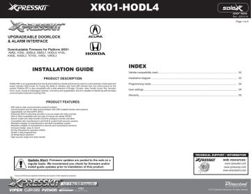
Xk01 Hodl4 Manualzz

Im05 Pkn2 Manualzz

After Market Remote Starter Ask The Gm Technician Gm Trucks Com

Xk01 Gmdl5x En Ig Vm20071129 Cdr Manualzz
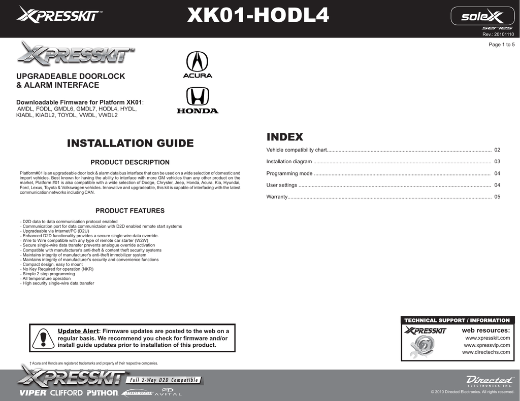
Xk01 Hodl4 Manualzz
Xk01 Bypass Stops Responding
Another Viper 5901 Rs Wiring Issue Tundra

Omega Security System Installation Instructions Manualzz
2002 2007 Trailblazer Remote Start Pictorial
