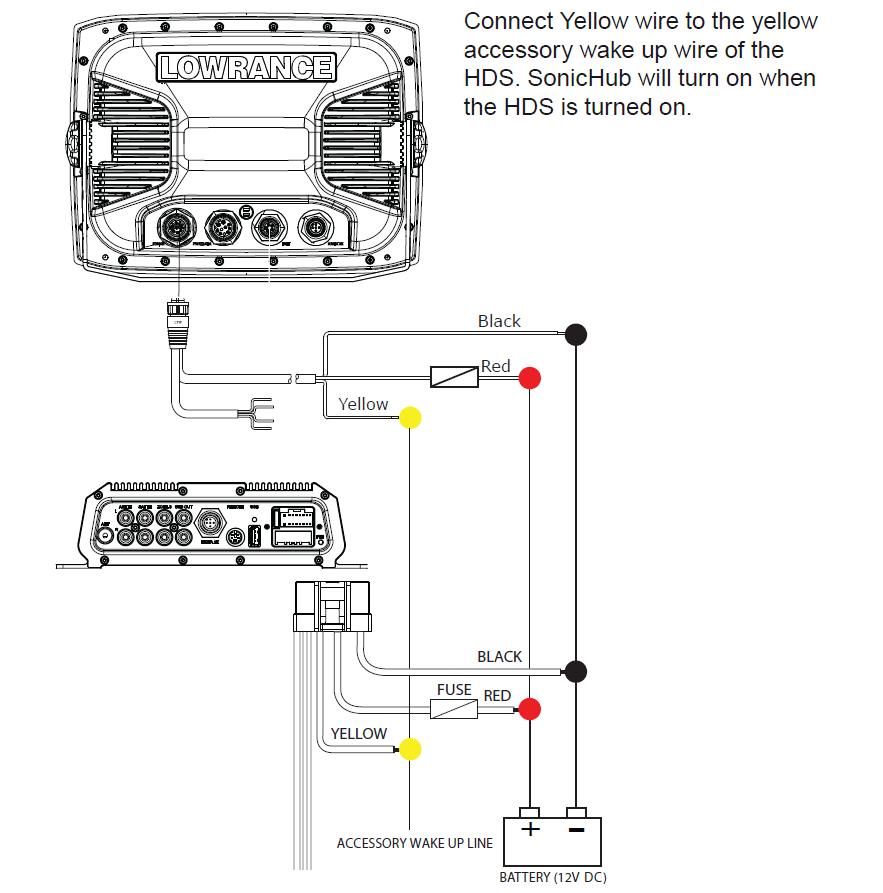
IMPORTANT BATTERY 12V DC ACCESSORY WAKE UP LINE FUSE RED BLACK YELLOW -Red Black Yellow Connect Yellow wire to the yellow accessory wake up wire of the HDS. A video camera may be added by installing the optional video adaptor cable.
Sonichub 2 Wiring Diagram - If you're looking for video and picture information linked to the key word you've come to pay a visit to the right site. Our site gives you suggestions for viewing the highest quality video and image content, hunt and find more enlightening video articles and graphics that fit your interests. includes one of thousands of movie collections from various sources, especially Youtube, so we recommend this video for you to view. You can also contribute to supporting this site by sharing videos and images that you enjoy on this blog on your social networking accounts like Facebook and Instagram or educate your closest friends share your experiences about the simplicity of access to downloads and the information you get on this site. This blog is for them to stop by this site.

Knowledge Base Simrad Sonichub To Two Hds Units
If you have not connected it to ground the unit you possibly have an open circuitno ground- no power.

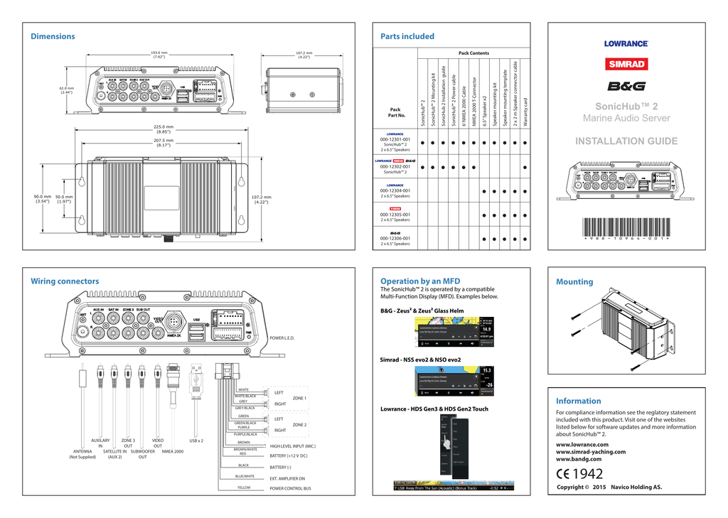
Sonichub 2 wiring diagram. Enjoy Bluetooth streaming from your smartphones or tablet audio and video playback from USB flash drives built-in AMFM radio and SiriusXM satellite radio US only all controlled from any Simrad multifunction display on board. SonicHub2 features integrated Bluetooth allowing you to stream music including Pandora from a smartphone or tablet. 2 Front - controls 3 Rear - connections 4 Hardware installation 4 Display mounting location 5 Display installation 7 Wiring 7 Guidelines 7 Power connection 8 Power Control connection 9 External alarm 10 Connect an external monitor 11 NMEA 2000 connection to backbone 12 NMEA 0183 device connection 13 Ethernet device connection 13 Video in.
Lowrange Mark-4 Chirp Wiring Diagram. SonicHub Deck Mount USB With 2M Cable. Im wondering if the old wiring was connected the Fusion device which I removed and with it cannot be switch on.
875 to 1080 MHzUS. The thickest of the two. It will do all that youre trying to accomplish feature wise but use it as the head unit only add amps and speakers to get the volume you want.
The SAT IN input can be from a WM-2. Black Yellow BLACK FUSE YELLOW ACCESSORY WAKE UP LINE. SonicHub will turn on when the HDS is turned on.
The Steer Downscan Sonar and Chart pages have menus that can only be. SonicHub will turn on when power is applied Always connect to power using a fuse or breaker 15 Amp. Wiring HDS Gen3 Installation Manual.
Line inputs 2V peak-to-peak. 2 Front - controls 3 Rear - connections 4 Hardware installation 4 Display mounting location 6 Display installation 7 Flush mounting 8 Transducer mounting location 9 Attaching the Transducer 10 Wiring 10 Guidelines 10 Power connection 10 Power Control connection 12 External alarm 13 Connect an external monitor 14 Connect sonar transducers. Add to cart View Product.
SonicHub2 is a complete audio entertainment system that integrates seamlessly with Simrad displays. The yellow wire in a newer 12 volt system is the ground. Add to cart View Product.
Add to cart View. It looks like the yellow wire is intended as some sort of signal to switch the power. This equipment NOTEThis manual covers Mark-4 Elite-4 Elite-5 Elite-7 and Elite- 9 units.
Connect Sat In Aux 2. Lowrance Structurescan Wiring Diagram Installation instructions for installing the Lowrance StructureScan HD processor module unit for a more panoramic view underwater. Add to cart View Product.
High level inputs max 6V 2V Typical Video out PAL and NTSCAntenna Connection. The SonicHub2 module works with Android devices and IOS devices with the Lightning connectorFM TunerJPN. LSS-1 module ethernet cable StructureScan transducer transducer mounting.
Water Resistant Marine Speakers 5995. SAT IN AUX 2 In. The plug of the supplied power cable has two discrete cables.
Wiring diagrams interfacing to lowrance hds gen2 3 diagram 7 5m installation manual pdf 12 gen review simrad help support sonichub elite 5 sonar hdi multiple hds9 touch the motor starter airpressor schematic question hull 2000c gps 4 hook 4x unit and accessories live power cord plug garmin 546s boat in a box 8 user with transducer nmea electronic. 760 to 900 MHzEU. Good point in general but the SonicHub still uses the redblack convention with the yellow wire as a power switch.
I am late coming to the party here. BLACK FUSE YELLOW SWITCH Optional BATTERY 12V DC Connect Yellow wire to the yellow accessory wake up wire of the HDS. Volume and balance can be controlled for this amplifier from the display or other Fusion controllers.
I was looking at the new SonicHub 2 wiring diagram. Simrad 65 Marine Speakers. The plug of the supplied power cable has two discrete cables exiting from it.
This includes the power wires as well as the speaker wires. As a result screenshots. AMP PWR ON Connect SAT IN AUX 2 Connect ZONE3 Zone 3 Is a stereo line level output that can be connected to a separate amplifier and speakers.
The speaker wires should be run from the SonicHub to the speakers and are attached by inserting the exposed wires into small clamps. As others have said its built in amp will probably not be enough. Cable wiring diagram in your HDS Installation manual for more information.
Lowrance And Simrad Yachting Debut Uni-Dock For SonichubOctober 08 2013Marine Electronics Leaders New Secure Watertight Media Dock Adds Support For Latest. The system has an integrated AMFM r. BG 65 Speaker Pair.
SonicHub will turn on when the HDS is turned on. CHIRP can be used with Lowrance conventional. The old unit was connected to a control from a company called Fusion fancy round LCD gizmo.
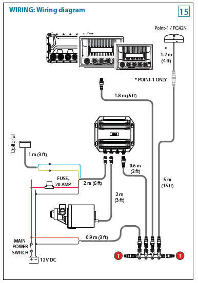
Connecting the black and red wires to HDS unit will give the SonicHub power and connecting the yellow wire will automatically activate the SonicHub when the HDS unit is powered on. Wiring the Sonic Hub 15 WM-2 WM-2 WEATHER MODULE AUXILARY 2 BLUE EXT. Protection against harmful interference in a residential installation.
On 11718 at 1052 am to RichJ. Sonichub 2 Wiring Diagram Diagram Data Schema Lowrance Gps Wiring Diagram Wiring Diagram Schema Blog Lowrance Elite 5 Hdi Wiring Diagram Inspirational Lowrance Hds Touch. 879 to 1079 MHz Aux InputOutputsAUX 1 In.

Lowrance Sonic Hub Wiring Diagram 1969 Corvette Wiring Diagram Coil Sportster Wiring Kebilau Waystar Fr
Sonic Hub Trouble The Hull Truth Boating And Fishing Forum
Diagram Wiring Diagram For Lowrance Hds 7 Full Version Hd Quality Hds 7 Tvdiagram Fanofellini It
Lowrance Sonic Hub The Hull Truth Boating And Fishing Forum

Knowledge Base Simrad Sonichub To A Single Hds Unit
Sonic Hub Owners And Or Electrical Engineers Texas Fishing Forum

Lowrance Hds 7 Gen 1 Manual
Simrad Sonichub 2 Sonichub 2 Install Installation Manual Manualzz
Lowrance Hds 5 Gen 1 Installation Manual
