Annunciator Panel by PANALARM 2 ea. After wiring 14-relay dry contact box to annunciator.
Panalarm Annunciator Wiring Diagram - If you're looking for picture and video information related to the key word you have come to pay a visit to the ideal blog. Our website gives you hints for seeing the highest quality video and picture content, search and locate more enlightening video content and images that fit your interests. includes one of thousands of video collections from several sources, particularly Youtube, so we recommend this video that you view. You can also bring about supporting this website by sharing videos and images that you enjoy on this site on your social networking accounts like Facebook and Instagram or tell your closest friends share your experiences concerning the simplicity of access to downloads and the information you get on this website. This site is for them to stop by this website.
Https Www Ametekpower Com Media Ametekpower Files Products Alarm Management Model 90a Annunciator Series 90a Manual Pdf Dmc 1 La En
ANNUNCIATOR AMETEKs Model 910 self-contained 10-alarm point annunciator is commonly used throughout the process industry.

Panalarm annunciator wiring diagram. 65 3m pps paint preparation system. NOTE Retain side panels and drill screws for reassembling. Panalarm Annunciator Series 90a Wiring - Installation and Operation Manual A-208 Alarm Annunciator wiring diagram Fig10.
Select from flush panel mounting or wall mounting type hardware to fit your physical installation. The NT2 has a decibel output of 88 db 10ft. This annunciator accepts ten dry or ten 120 VAC wetted field contact inputs.
70 3M Hi-Strength Postforming 94 CA Cylinder Spray Adhesive. Storage-40 to 85C -40 to 185F. Annunciator Panel by PANALARM 2 ea.
Panalarm 910 annunciatorpanalarm acs8. RS-485 Serial Modbus RTU communication standard and Ethernet Modbus TCPIP communication optional. Not only do the 42 inputs and 11 outputs make the SEL-2523 Annunciator Panel a great fit for traditional annunciation but programmable logic and up to four communications ports supporting DNP3 Modbus and SEL protocols allow it to make easy work of your most demanding applications.
2001 ford escape 3 0 v6 just installed used engine won u0026 39 t. The Series 90 annunciator system is a. Annunciator Panel Contained in a compact NEMA 4 enclosure the audible and visual alarm annunciator is a companion to the PE Series power enclosures and features eight Form-C alarm relays.
Surface-Mount Annunciator Installation 1. Remove the side panels and separate front and back annunciator panels. The horn is available in four models NT2-12D NT2-24D NT2-120A and NT2-230A.
Find all manuals for Chatillon and Lloyd Instruments force testers and materials testers here. REPLACED BY SERIES 90B. The Series 90 system is designed for optimum versatility and a universal busing and interconnect system which allows for virtually unrestricted arrangements and intermixing of electronic modules in any.
20 SPECIFICATIONS System Voltage. Designed for simple installation and operation the 301C continuously monitors and controls toxic gases combustible gases and oxygen hazards. Simplify commissioning and troubleshooting.
It also provides the user a choice of 16 different field selectable tones. Field Contact Options24 Vdc Dry Contact 48 125 250 Vdc 20 live input or opto-isolated 115 240 Vac two-wire input H and N. Panel australian wiring diagrams how to use house electrical plan software fire alarm annunciator wiring for 50rz262 smokstak alternator failure warning in piper pa28 aircraft david annunciator beeper amp buzzer schematics electronics how to use house electrical plan software electrical and fci lcd 7100 wiring diagram free wiring diagram 900 0301 i7 201101tp cumminsthe annunciator units can be.
AC Power Failure Low Battery Charger Failure BDA Failure and Antenna Failure. We offer an extensive sales and service network around the globe including the US UK and Asia. Consult factory for extended ranges.
Proceed to Annunciator Wiring section following. We can provide fault recorders power line carriers high accuracy revenue meters alarm. Annunciator panel wiring diagram.
AMETEK Power Instruments serves the world-wide electric power generation and distribution industries with our advanced instruments and monitoring systems. SACO 128R4 Circuit diagram relay module 7 English - dxf - Circuit diagram SACO 128R4 Circuit diagram relay module 8 English - dxf - Circuit diagram SACO 148D4 Circuit diagram sheet 14 English - dxf - Circuit diagram. Panalarm series 70 manual pdf.
Ten alarm points of dedicated annunciation at its best. The Series 90 annunciator system is a monitoring system designed to provide status information of discrete signal contacts and provide interface and monitoring of commonly used analog devices. Digital Ametek - Official Site - AMETEK is a global leader in electronic instruments and.
5 user-defined inputs and Locate panels at multiple locations. Panalarm Annunciator Series 90a Wiring - Installation and Operation Manual A-208 Alarm Annunciator wiring diagram Fig10. Based on the highly acclaimed Series 90 AMETEKs new Series 90A Annunciator brings alarm monitoring Opertaion Manuals.
Operating-40 to 60C -40 to 140F. Model 57This Ametek Panalarm 94CA-34 Annunciator Module is used and in excellent Datasheets Manuals Ametek Panalarm Series 90 Annunciator Systems. The horns are commonly used as the audible device associated with one of AMETEKs annunciator systems.
Powder coated ms or aluminum rack panels with quality panel wiring. Logic Lamps24 Vdc 20. Return to this section after wiring annunciator.
Above installation and operation manual a 208 alarm annunciator wiring diagram fig 10 1 ea annunciator panel by panalarm 2 ea digital rtk s ser substation annunciator now kema certified to iec 61850 this panel mounting annunciator is capable of capturing critical alarms to 1ms resolution to. 10 Panalarm Annunciator Wiring Diagram Pictures. Monitor generator faults and status and option to monitor 1 ATS or up to 4 ATS.
For Legacy RTU RTU Alarm Annunciator. Panalarm series 100. Using an addressable RS-485 Modbus communication protocol the 301C uses daisy chain wiring requiring only 2 pairs of wires to connect up to 96 transmitters on the 3.
Meets NFPA 110 for critical facilities. Start and stop a. The first five alarms are wired for NFPA mandated alarms.
69 Spray Guns Accessories. 65 3M PPS Paint Preparation System.
.JPG)
Miscellaneous Other Manufactur Ametek Panalarm Alert Panel
Https Www Mtl Inst Com Images Uploads Sub Station Annunciator Instruction Manual Rev 4 Pdf

Panalarm 94ca Annunciator Used Metal Logics Inc
Http Www Grpeters Com Litera Ametekpi Panalarm 20model 20910 Pdf
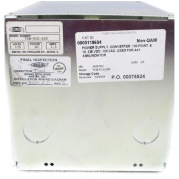
Ametek 70b Pcd 100 Ims Supply

Miscellaneous Other Manufactur Ametek Panalarm Alert Panel

Panalarm Series 910 Annunciator Module 910ac120e1h1wb1 Used
Ul Listed Conventional Fire Alarm System Supplier Company Price Bangladesh Service Provider Bd Conventio Fire Alarm System Fire Alarm Fire Protection System
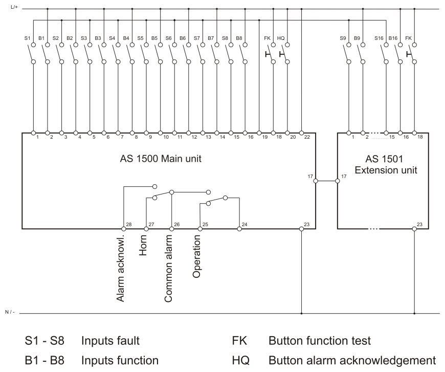
Diagram Wiring Diagram Of Annunciator Full Version Hd Quality Of Annunciator Diagramati Mbreporter It
