Assortment of ge shunt trip breaker wiring diagram. Feature a remote-close solenoid and either a shunt trip with or without lockout or undervoltage release accessory is also.
Ge Shunt Trip Breaker Wiring Diagram - If you're searching for video and picture information related to the keyword you've come to visit the ideal blog. Our website provides you with suggestions for viewing the highest quality video and picture content, hunt and locate more informative video content and images that match your interests. includes one of tens of thousands of video collections from various sources, especially Youtube, therefore we recommend this video for you to view. This blog is for them to visit this site.

We Engineers Shunt Trip Function In Detail
1 trick that I use is to printing the same wiring.
Ge shunt trip breaker wiring diagram. The neutral wire is connected to the shunt coil. A wiring diagram is a simplified traditional pictorial depiction of an electric circuit. Now GE introduces Power Break II insulated case circuit breakers the vanguard of a new age in reliable flex-.
The other wire connects to one side of the dry contactauxiliary on the Ansel system. It shows the elements of the circuit as simplified shapes as well as the power as well as signal connections in between the gadgets. A shunt trip must be installed in the circuit breaker before the cir- cuit breaker is mounted in an electrical system Route wiring to meet installation requirements.
A wiring diagram is a simplified standard photographic depiction of an electric circuit. Ge Shunt Trip Breaker Wiring Diagram wiring diagram is a simplified pleasing pictorial representation of an electrical circuit. Wiring Diagram Secondary Terminals.
It reveals the elements of the circuit as simplified forms as well as the power and signal connections in between the gadgets. Shunt Trip ST The shunt trip opens the circuit breaker when its coil is energized by a voltage input see Table 1. GE Industrial Systems makes no representation or warranty expressed implied.
One of the wires if there is a white one connects to the neutral bar. A wiring diagram is a streamlined standard. The incoming 3 phase 4 wire system supply shown.
When you use your finger or the actual circuit together with your eyes its easy to mistrace the circuit. You can also look for some pictures that related to Wiring Diagram by scroll down to collection on below this picture. It reveals the elements of the circuit as simplified forms as well as the power and signal connections in between the gadgets.
The shunt breaker is 3 pole. A wiring diagram usually provides details regarding the family member. It shows the components of the circuit as simplified shapes and the faculty and signal contacts in the company of the devices.
Which is also known with the name of kill switch. 120v to 240v for the 1021 suffix to the two terminals on the shunt trip. Do this just like you would with a regular circuit breaker.
Collection of square d shunt trip breaker wiring diagram. Collection of ge shunt trip breaker wiring diagram. Ge Shunt Trip Wiring Diagram Data Wiring Diagram Shunt trip device for type ted thlc1 and tlb1 circuit breakers geh 3 416 keywords.
It is supplied with yellow and white secondary leads connected to a secondary connector plug see Figure 2. And line wire is controlled with a kill switch. So neutral is required also.
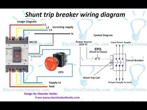
Shunt Trip Breaker Wiring Diagram Motherwill Shunt Trip Breaker Wiring Diagram Wiring Diagram includes numerous detailed illustrations that show the relationship of varied items. In the above MCCB shunt trip breaker wiring diagram. Here is some images of shunt coils and after that we will discuss the shunt trip breaker wiring diagram with image symbol diagram.
Now lets how to wire shunt trip device accessory its too simple as i shown in above shunt trip device images that a shunt coil have only to wires just like a magnetic contactor or magnetic relay coil. But the coil of the shunt is 220 VAC. Shunt trip breaker wiring diagram this post is about the single wiring diagram of mccb shunt trip breaker.
A wiring diagram is a streamlined standard photographic representation of an electrical circuit. A shunt trip is an accessory not a type of breaker. Shunt breaker wiring diagram Relay Wiring Diagram 8 Pole Best Siemens Shunt Trip Breaker Wiring Diagram Elvenlabs.
The two wires that come out of the shunt breaker are the trip circuit wires. A wiring diagram is a streamlined traditional pictorial representation of an electrical circuit. It contains directions and diagrams for different varieties of wiring techniques along with other items like lights home windows and so on.
It shows the parts of the circuit as simplified forms and also the power and also signal connections between the tools. Diagram Shunt Trip Circuit Breaker Wiring Full Version Hd Quality Mediagrame Patriziaprestipino It Electrical 240 Volt Bolt On 3 Phase 4 Wire Panel Main Lug Only W 7 Pole Circuit Breakers From 15 To 100 Amp. It shows the elements of the circuit as streamlined forms and the power as well as signal connections between the devices.
Ge Shunt Trip Breaker Wiring Diagram. Which is used for the 3 phase system. Ge shunt trip breaker wiring diagram.
Variety of ge shunt trip breaker wiring diagram. Undervoltage Release UVR The undervoltage release opens the circuit breaker. Shunt trip wiring diagram square d Fancy Siemens Shunt Trip Breaker Wiring Diagram 54 With Additional 2001 Jeep Grand Cherokee Radio To.

Madcomics Shunt Breaker Wiring Diagram
How To Connect Shunt Trip Breakers Youtube

Madcomics Shunt Breaker Wiring Diagram

Madcomics Shunt Breaker Wiring Diagram

Shunt Trip Breaker Wiring Diagram Get Image About Wiring Auto Electrical Wiring Diagram
Shunt Trip Breaker Wiring Diagram In Urdu Hindi How To Install A Shunt Trip Breaker Youtube

Madcomics Shunt Breaker Wiring Diagram

Pin On Amp

Madcomics Shunt Breaker Wiring Diagram
