More information on proper wiring and grounding techniques. 2 wire maximum per terminal screw Solid 14 to 22 AWG Stranded 16 to 22 AWG Important.
1766 L32awaa Wiring Diagram - If you're searching for video and picture information related to the keyword you've come to visit the right site. Our site provides you with suggestions for viewing the highest quality video and picture content, search and locate more enlightening video content and images that match your interests. includes one of thousands of video collections from several sources, especially Youtube, therefore we recommend this video that you view. It is also possible to bring about supporting this website by sharing videos and graphics that you enjoy on this blog on your social media accounts like Facebook and Instagram or educate your closest friends share your experiences concerning the ease of access to downloads and the information that you get on this website. This blog is for them to visit this site.

Controller I O Wiring Minimizing Electrical Noise Rockwell Automation 1766 Lxxxx Micrologix 1400 Programmable Controllers User Manual User Manual Page 52 406
Sinking and Sourcing Wiring Diagrams.
1766 l32awaa wiring diagram. Wiring Diagrams Type Definition Sinking Input The input energizes when high-level voltage is applied to the input terminal active high. Page 51 Wire Your Controller Chapter 3 Figure 7 - 1766-L32BWAL32BWAA Sinking Input Wiring Diagram DCa DCb DCc 24V DC Sensor Power -DCa -DCb -DCc DC OUT - 24V COM 0 COM 1 COM 2 IN10 IN11 1766-L32BWAA. Important User Information Solid-state equipment has operational characteristics differing from those of electromechanical equipment.
If the input device only includes a Voltage input it can be easily adapted to measure a 4-20mA signal by adding a 250 Ohm load resistor across the Positive and Negative - Input connections. The examples and diagrams in this manual are included solely for illustrative purposes. The input and output terminals of the MicroLogix 1000 controller are designed for the following spade lugs.
Wiring Diagram August 24 2017. The diameter of the terminal screw head is 55 mm 0220 in. Secure the battery connector wires so that it does not block the 1762 expansion bus connector as shown below.
Modules can be either DIN Rail or panel mounted. Installation Instructions publication 1766-IN001. ONNECT XPANSION-ODULES Connect 1762 IO after mounting the controller.
Rockwell Automation Publication 1766-UM001H-EN-P - May 2014. Because of the many. The1763-L16BBB is a DC power supply with a 24V input supply voltage and an input current of 15AIt also has a power consumption of 35W and is fitted with an FET standard output.
Because of the many. 36 1766-L32BWA 1766-L32AWA 1766- L32BXB 1766-L32BWAA 1766-L32AWAA. The Allen-Bradley 1763-L16BBB MicroLogix 1100 is a programmable controller with a 90 mm 35 in x 104 mm 409 in x 110 mm 433 in dimension and a net weight of 09 kg 20 lbsIt has 6 outputs and 12 inputs.
Industrial Automation Wiring and Grounding Guidelines publication 1770-41. Page 4-18 Removed catalog 1761-NET-DNI Chapter 4 Added 1764-MM3 and 1764-MM3RTC to catalog table and new footnote. 1766-L32AWAA 1766-L32BWA 1766-L32BWAA 1766-L32BXB 1766-L32BXBA.
Information on installing and using the MicroLogix 1400 programmable controller. Page 6-1 Added 1764-MM3RTC to footnote for Table A1 General Specifications Page A-2 Updated Operating Frequency for 1764-24BWA and 1764-28BXB. Any of the MicroLogix 1400 DC embedded input groups can be configured as sinking or sourcing depending on how the DC COM is wired on the group.
Information on installing and using the MicroLogix 1400 programmable controller. The modular rackless design enhances cost savings and reduces replacement parts inventory. Remove the expansion port cover to install expansion IO modules.
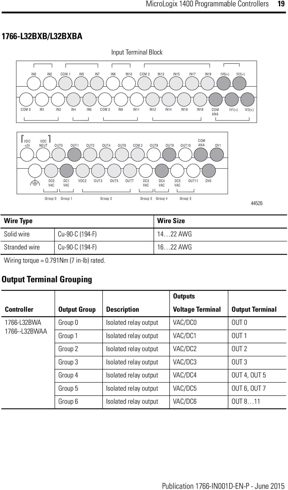
1766-L32BWA 1766-L32AWA 1766-L32BXB 1766-L32BWAA 1766-L32AWAA 1766-L32BXBA Wiring Diagrams. Catalog Numbers 1766-L32BWA 1766-L32AWA 1766-L32BXB 1766-L32BWAA 1766-L32AWAA 1766-L32BXBA. Once wiring is complete remove protective debris strip.
Table Of Contents Installation Instructions MicroLogix 1400 Programmable Controllers Catalog Numbers 1766-L32AWA 1766-L32AWAA 1766-L32BWA 1766-L32BWAA 1766-L32BXB 1766-L32BXBA Topic Page Important User Information Additional Resources Overview Controller Description Hazardous Location Considerations Mount the Controller Connect 1762 IO Expansion Modules Wire. Micrologix 1400 1766 L32Awa1766L32Awa with regard to Micrologix 1400 Wiring Diagram. All wiring must comply with NEC.
Here is a picture gallery about 1766 l32awa wiring diagram complete with the description of the image please find the image you need. Article 501-10b andor in accordance with. Literature Library Rockwell Automation.
Liability for actual use based on the examples and diagrams. The examples and diagrams in this manual are included solely for illustrative purposes. Our Bulletin 1762 MicroLogix Expansion IO Modules extend the capabilities of the MicroLogix 1100 1200 and 1400 controllers by maximizing flexibility of the IO count and type.
Page A-3 Added Relay Output life to. Customers Recording Device 7-30 VDC Power Supply White Black I I 4-20 mA Meter Output 4-20 mA 4-20 mA Module Terminal Connections Wires from EDM Cable from Customer Equipment Red White Black Not Used Red I Loop Black I Loop White Wires from EDM. 1766 L32Awa Wiring Diagram 1766-Mm1 Wiring Diagrams Techwomenco pertaining to 1766 L32Awa Wiring Diagram image size 582 X 449 px image source.
1766-L32AWAA 1766-L32BWA 1766-L32BWAA 1766-L32BXB 1766-L32BXBA. Chapter 3 Wire Your Controller. Installation Instructions publication 1766-IN001.
Failure to remove strip. WIRING This is the wiring diagram for the 4-20 mA output. More information on proper wiring and grounding techniques.
Wiring Your Controller Wire Type. Plug the ribbon cable connector into the bus connector444. Updated wiring diagram for 1761-CBL-PM02.
MicroLogix 1766-L32BWA 1766-L32AWA 1766-L32BXB 1766-L32BWAA 1766-L32AWAA 1766-L32BXBA Input Power 120240 V AC 24V DC 120240 V AC 24V DC Memory non-volatile battery backed RAM User Program User Data Space 10K 10K confi gurable Data Logging Recipe Storage. Industrial Automation Wiring and Grounding Guidelines publication 1770-41. This will generate a voltage drop of between 1 and 5 Volts which is directly proportional to the 4-20mA signal.
Micrologix 1400 Programmable Controllers Pdf Free Download

Plc Micrologix 1400 1766 L32bwaa 1766l32bwaa Ec91085868

Plc Micrologix 1400 1766 L32bxba 1766l32bxba Ec91085868
Http Repository Usu Ac Id Bitstream Handle 123456789 72170 Fulltext Pdf Sequence 1 Isallowed Y

Sinking And Sourcing Wiring Diagrams Rockwell Automation 1766 Lxxxx Micrologix 1400 Programmable Controllers User Manual User Manual Page 50 406

Plc Micrologix 1400 1766 L32bwa 1766l32bwa Ec91085868
Http Repository Usu Ac Id Bitstream Handle 123456789 72170 Fulltext Pdf Sequence 1 Isallowed Y

Micrologix 1400 Programmable Controllers Pdf Free Download

Micrologix 1400 Programmable Controllers Pdf Free Download
