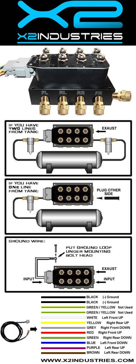
Interconnecting wire routes may be shown approximately where particular receptacles or fixtures must be upon a common circuit. Red Front left down Brown Rear left down Purple Front left up Yellow Rear left up Grey Front right down White Rear right down Blue Front right up.
Vu4 Wiring Diagram - If you're searching for picture and video information related to the keyword you have come to visit the ideal site. Our site provides you with hints for seeing the highest quality video and picture content, search and locate more enlightening video articles and images that fit your interests. comprises one of thousands of video collections from several sources, particularly Youtube, so we recommend this movie for you to see. You can also contribute to supporting this site by sharing videos and images that you enjoy on this blog on your social media accounts like Facebook and Instagram or tell your closest friends share your experiences concerning the ease of access to downloads and the information that you get on this site. This blog is for them to stop by this website.

Air Ride Suspension Vu4 Wiring Harness Connects China Wiring Harness Connects Wiring Connects Made In China Com
12 Volt On-off safety switch Controls 8 valves individually Wiring Length.

Vu4 wiring diagram. 3 Drill holes with a 316 drill bit and bolt the VU4 down with the included 10-24 Allen head cap-screws. A wiring diagram usually gives opinion approximately the relative perspective and accord of. This pictorial diagram shows us the physical links that are far easy to understand an electrical circuit or system.
Plugs directly into any AVS ARC-7 or AVS ARC-T7 switchbox and Accuairs VU4 manifold valve. AVS VALVE WIRING HARNESS 10 15 20 - ACCUAIR VU4 VALVE TO AVS 7-SWITCH BOX AVS brand plug and go wiring harness. A wiring diagram is a visual representation of components and wires related to an electrical connection.
3 Drill holes with a 316 drill bit and bolt the VU4 down with the included 10-24 Allen head cap screws. If you have two lines from tank. Accuair vu4 wiring diagram.
1 Find a flat location to mount the VU4. 1 Find a flat location to mount the VU4. 2 Transfer hole pattern from the VU4 Mounting Template on page 22.
Mounting Wiring Installation System Diagram Terms Conditions Install Overview - Page 13 - AccuAir TouchPad Controller Installation Manual V AccuAir Control Systems LLC. ENDO-T and ENDO-VT Fastener torque specifications Table 3. Air Ride Switch Box Wiring Diagram.
Vu4 wiring chart drop-in 2009 accuair control systems llc. 2 Transfer hole pattern from the VU4 Mounting Template on page 14. VEHICLE MOUNTING Your ENDO Tank system has been designed to use AccuAirs unique Quick Release QR mounting system.
25meterscan extended length Wiring Diagram. Wiring diagram chevy 350 ignition wiring diagram 2016 nissan 370z. 2 Transfer hole pattern from the VU4 Mounting Template on page 14.
Basic Air Bag Set Up Diagram Air Ride Automotive Mechanic. For use with e-LevelTM Controller or any other brand of controller or switches. This electronic solenoid valve unit inflates and deflates up to 4 individual air springs and has built-in push-to-connect 38 DOT approved air.
Put ground loop under mounting bolt head ground wire. Avs Valve Wiring Harness 10 15 20 Universal To Avs 7 Switch Box. This should allow enough room for the airlines to be inserted without too much bending.
This should allow enough room for the airlines to be inserted without too much bending. 3 Drill holes with a 316 drill bit and bolt the VU4 down with the included 10-24 Allen head cap screws. If you have one line from tank.
7 Mount the single black wire labeled EC_GND with the VU4 ground. VU4 4-Corner Solenoid Valve Unit by Accuair The VU4 4-Corner Valve Unit is engineered to provide the cleanest installation and most reliable operation on the market. Electrical specifications for the ENDO-VT product line.
Actual product may differ from pictures. 4800 9600 19200 38400 57600 or 115200 bps. 7 Switch Box Controller For VU4 Valve Voltage.
6 Route the single red wire labeled BATT_12V with a 10 Amp fuse to the vehicle battery. 1 Find a flat location to mount the VU4. The AA-VU4 Corner Valve Unit is engineered to provide the cleanest installation and most reliable operation on the market.
This should allow enough room for the airlines to be inserted without too much bending. It works with a 2 pump 3 pump or 4 pump setup. SlaveMaster Mode Slave address range 1-255 or Setpoint master mode.
On Bad Boy Buggy Xt Battery Wiring Sater Light Switch Buggy. Odd even or no parity. It shows the components of the circuit as simplified shapes and the knack and signal friends surrounded by the devices.
Basic Air Bag Set Up Diagram Air Ride Automotive Mechanic. Architectural wiring diagrams behave the approximate locations and interconnections of receptacles lighting and remaining electrical facilities in a building. 8 Route the single blue wire labeled E-BRAKE to the ground triggered.
Connection via rear terminals refer to wiring diagram. Insert black plug into inlet. 8 data bits and 1 stop bit.
1 Find a flat location to mount the VU4. High Pressure Rated for operation up to 200 psi. Good replacement to Accuair AA-VU4 Air suspension valve block With E-level Compatiable Suspension Type.
Air Ride solenoid Wiring Diagram wiring diagram is a simplified conventional pictorial representation of an electrical circuit. This should allow enough room for the airlines to be inserted without too much bending. 14 NPT ports for more flexibility of installation.
3 Drill holes with a 316 drill bit and bolt the VU4 down with the included 10-24 Allen head cap-screws. Locates in Option Slot A. Here are a couple of diagrams i made up for one of my friends who wanted to get into air ride but didnt quite understand all the basics.
Written ByadminMonday April 20 2020Edit. Requires external manifold and valves like the AccuAir VU2 or VU4. This electronic solenoid valve unit inflates and deflates up to 4 individual Air Springs and has built-in push-to-connect 38 DOT.
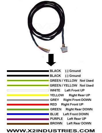
Standard length is 10-foot. 5 Route the single yellow wire labeled COMP_1 with a 3 Amp fuse to trigger the Compressor Relays. Its more smart than our previous manifolds Assembly Valve Block wiring harness 160-4F Solenoid Valve.
Approved air fittings for all of its plumbing connections. Pre-wired Port Numbered for reduced installation time. 2 Transfer hole pattern from the VU4 Mounting Template on page 22.
15 Foot Accuair Vu4 To Arc 7 Switch Box Extension Cable X2 Industries

Vu4 Wiring Diagram Accuair Vu4 4 Corner Solenoid Valve Unit W 1 4 Npt Ports

Avs Valve Wiring Harness 10 15 20 Avs Evolve Accuair Vx4 Valve To Avs 7 Switch Box Avs

Vu4 Wiring Diagram

10 Foot Accuair Vu4 To Arc 7 Switch Box Extension Cable Universal Air Ride
Accuair Vu4 Valve To Arc 9 Switchbox Air Ride Bag Avs Wiring Harness 15

China Air Ride Suspension Vu4 Wiring Harness Connects China Wiring Harness Connects Wiring Connects
Accuair Clone Single 4 Corner 8 Way Valve Block Assembly X2 Industries
Wiring Diagram Billet Rev 3 Air Suspension
