Wiring layouts are made up of 2 things. Return to the front of the UTV to mount the ground wire.
Utv Horn Wiring Diagram - If you're searching for picture and video information linked to the key word you have come to pay a visit to the right blog. Our site gives you hints for seeing the maximum quality video and picture content, search and locate more enlightening video articles and graphics that fit your interests. includes one of thousands of video collections from various sources, particularly Youtube, therefore we recommend this movie for you to see. You can also bring about supporting this website by sharing videos and graphics that you like on this blog on your social media accounts like Facebook and Instagram or tell your closest friends share your experiences concerning the simplicity of access to downloads and the information that you get on this website. This site is for them to visit this site.

Electronic Blinker Relay Cf13 002 2allbuyer Motorcycle Wiring Wiring Diagram Relay
Diagram Wiring For Blinkers Full Version Hd Quality Printerdiagram Cefalubb It.

Utv horn wiring diagram. Find an existing bolt on the frame that would make a good ground. I have everything wired according to this diagram. The two wires going to the stock horn would go to terminals 8586 on the relay.
Final Wiring of components25 Female Spade Terminal End for 18 22 Gauge Wire Joins ground wire from signal indicator light black or white to white ground wire from. The pink wire on the horn button actually provides the ground to the horn. Location C as shown in figure.
Connect the harness 1 to the. If you take the time to read installation instructions you should find recommended wire sizes and lengths on most reputable electrical gear. Or debris can drain from the horn.
Heres the wiring schematic. Take care when drilling to avoid damage to any components behind the dash. Icons that represent the components in the circuit and lines that stand for the links in between them.
Connect the horn button to the green and black wires from the wiring harness. Wires for the switch. When autocomplete results are available use up and down arrows to review and enter to select.
Results 49 - 96 of Mahindra MpacIntimidator 20 HALF WINDSHIELD Fits. You can bend andor drill the horn bracket for a custom fit. So I sat down and drew out a simple diagram for turn signals and on the UTV since I really didnt want to interrupt the existing wiring and.
Protect the finish of the UTVs. This same process could be followed for installing a fuse box i. Connect the wiring harness to a power source.
When autocomplete results are available use up and down arrows to review and enter to select. Diagram Hazard And Turn Signal Switch Wiring Full Version Hd Quality Bpmdiagrams Umncv It. Remembering that many of the 50s British cars had dash-mounted toggle switches for turn indicators and even some of the new UTVs are doing the same thing I decided that a toggle switch would work just fine.
Touch device users explore by touch or with swipe gestures. Diagram Turn Signal Wire Full Version Hd Quality Soadiagram Assimss It. 12v HORN for SXS UTV Turn Signal Kit Wiring Diagram for DIY All.
White from flasher harness joined with ground from turn signal indicator to negative ground side. It shows the components of the circuit as simplified shapes and the aptitude and signal links in the middle of the devices. Touch device users explore by touch or with swipe gestures.
Results 49 - 96 of Mahindra MpacIntimidator 20 HALF WINDSHIELD Fits. I am using a Carling Actuator Horn Switch same one from old horn and I cannot get the horn to honk. Its very easy to get puzzled regarding wiring diagrams and schematics.
Black Universal Turn Signal Switch Golf Cart Atv Utv Side By Rhino A. In this video Garrett takes you through the process of installing a fuse box in his Teryx 4. Going directly to the battery allows operation with the ignition off or connect to the ignition switch or accessories power bar on your UTV.
Route the harness from under the hood and dash through the hole drilled in Step 5. On the RZR shown below we found an existing hole in the frame and bolted our horn to it bolt not included. May 11 2018 - Great Wiring Diagram For Horn Relay HORN RELAY Simple Wiring.
A wiring diagram is a kind of schematic which uses abstract pictorial symbols to show all the affiliations of components in a system. HS700 UTVHS600UTVHS500UTV WIRING DIAGRAM. It doesnt matter which terminals these wires are connected to.
Make a 6 inch ground wire using the included Black Wire. If your product calls for a 14-gauge wire then stick. I have power where it should be but nothing.
Locate and Turn Signal Switch and the LED Turn Signal Indicators. Then run a wire from the positive battery through a fuse to terminal 87 on the relay. I consider myself pretty mechanically inclined but wiring this horn is driving me nuts Attached is the diagram I used to wire the new Euroblast Air Horn.
The horn will work correctly either way. Using the Horn Mounting Kit attach the horn to the frame or metal tubing of your UTV. REVIEW THE WIRING DIAGRAM ON PAGE 4.
Once you have the horn mounted connect the red and green wires coming off of the harness into the two spades on the horn. May 11 2018 - Great Wiring Diagram For Horn Relay HORN RELAY Simple Wiring. Attach one of the Female Spade Connectors on one end and a 10 Ring Terminal to the other end.
12v HORN for SXS UTV Turn Signal Kit Wiring Diagram for DIY AllThe Dux Deluxe Signal kit includes clockwise from top instructions a wiring harness with sheave and flasher unit decibel horn column-mounted signal switch with horn button six amber LED lights LED turn-indicator light tie-wraps brake-light. 12 Volt Horn Wiring Diagram wiring diagram is a simplified within acceptable limits pictorial representation of an electrical circuit. Using 58 drill bit drill a hole in the dash for the horn switch.
To mount the horn find a suitable location under the hood. There should be a brownswitched 12V wire going to the other terminal on the horn. The Horn will attach to the metal arm using a 14 nut.
Terminal Block Orange wire from harness to positive side. Section 8 diagrams wiring diagram terminal blocks 12v constant 12v ground 48v ground switched 12v lights switched 48v 650cc 479cc honda 265cc 277cc gasoline models gasoline models 48 volt electric models gasoline models-ground-ground 12v constant accessories switched 12v lights switched 12v 12v constant-ground-ground. CHAPTER 9 HS600UTV SERVICE MANUAL.
Signal Lights YellowWhite From harness.

12x Round 12v Blue Led Rocker Switch Toggle Car Spst Ebay Inside Wiring Diagram Toggle Switch Switch

Pin On Diagram
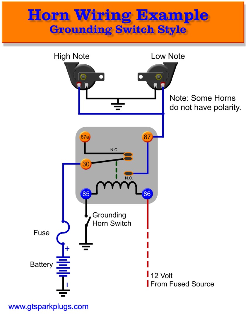
Diagram Piaa Horn Wiring Diagram Full Version Hd Quality Wiring Diagram Odiagrami Fanofellini It

Pin On Radia

How Do I Wire Up A 2pin Blinker Can In 2021 Wiring Diagram Relay Indicator Lights

Mictuning Ls09901 7 Pin Momentary Laser Rocker Switch Winch In Out 20 Amp 12v Light Blue In 2021 Wiring Diagram Switch Rocker

Tvs Apache Wiring Diagram Dolgular Com At In Tvs Apache Wiring Diagram In 2021 House Wiring Wiring Diagram Electrical Panel Wiring

17 Car Horn Relay Wiring Diagram Auto Mecanica Fiacao Eletrica Auto
Automotive Wiring Diagram Symbols Electrical Wiring Diagram Electrical Diagram Electrical Symbols
