Switch on the power and point the wind vane to the dead ahead position. Please see the wiring diagrams under the documents tab above for more details.
Clipper Wind System Wiring Diagram - If you're looking for video and picture information related to the keyword you have come to pay a visit to the ideal site. Our website provides you with suggestions for seeing the highest quality video and image content, hunt and locate more informative video articles and graphics that match your interests. includes one of thousands of video collections from several sources, especially Youtube, therefore we recommend this video that you view. It is also possible to contribute to supporting this website by sharing videos and graphics that you like on this site on your social networking accounts such as Facebook and Instagram or educate your closest friends share your experiences concerning the ease of access to downloads and the information that you get on this site. This site is for them to visit this site.

Xrm7 Engine Diagram Wiring Diagram Honda
Connecting to the clipper true wind display then connect as shown in FIG-2b.

Clipper wind system wiring diagram. Using a short length of wire touch the ends to the tops of the screws clamping the blue and the black wires of the wind sensor. Wind System Clipper-Target-Cruiser V20 12pp A5 Pinkcdr. The Nasa Clipper Wind system shares the same 110mm square case as its sister instruments in the Clipper range.
Item wire color wire. Most of the processing of wind speed and direction is done within the display unit which takes signals. Midnite can custom build other resistance values upon request and has designed an easy to change resistor insert for the Clipper allowing changes in the field.
The Clipper Wind system shares the same 110mm square case as its sister instruments in the Clipper range. This cable provides one differential nmea 0183 input and output port. Openwind - Open Source Anemometer for sailing Test and Review.
CS - Compact and waterproof NMEA compass sensor transmits NMEA 0183 sentence HDG to Clipper Target and Cruiser or other equipment. The Clipper Compass Repeater is a fully independent display with all of the functions of the master unit. All thats at the free end of the wire are a red black blue and white wire along with the shielding.
The AC Clipper contains two 277 VAC 50 Amp 3 phase AC breakers one for a stop switch and a 1200 volt 200 Amp 3 phase bridge rectifier. Or Metressecond Nasa Cruiser Wireless Wind System. PSI covers the critical electronic hydraulic and precision mechanical components that drive the turbines pitch and yaw systems and down-tower electronics.
Note - if a magnetic variation value is programmed in the master unit ensure the repeater is set to the same value. Gimballed to - 30 degrees. Commonly repaired components include printed circuit boards pitch drive systems inverters IGBTs PLCs VRCC units.
It is wise to use a fused supply to provide protection should a fault occur. SETTING DEAD AHEAD To calibrate the direction. The thicker black cable contains the five wires that send power and receive signals to and from the masthead unit.
Please see the wiring diagrams under the documents tab above for more details. Windspeed is shown in knots MPH. The display is exceptionally large and clear with 60 segments for full 360 degree direction indication.
The AC Clipper contains two 277 VAC 50 Amp 3 phase AC breakers one for a stop switch and a 1200 volt 200 Amp 3 phase bridge rectifier. Clipper-Target-Cruiser V2 Wind systems. The display is exceptionally large and clear with 60 segments for full 360 degree direction indication.
The current consumption is very small so any supply with at least a 4 amp fuse is more than adequate. Requires NMEA boat speed input either VHW from log or RMC from GPS for True wind speed and direction. Follow the Clipper Compass instructions to complete this function.
SUPPLY Figure 1 - Wiring Installation 2. Openwind is a wind measuring device - An Open Source Anemometer designed for sailing kitesurfing windsurfing sailboats and any other reason to check on your weather and wind speed. Buy Clipper Wind Version 2 from Mazzeonautica on Amazon.
See the table and wiring diagrams when connecting the data cable to nmea 0183 devices. Accuracy - 2 degrees. The slim red and black power supply cores of the NASA Clipper display unit will need to be attached to a 12V-14V power supply scroll down for the full buyers guide.
Hello still unable to get my clipper wind sensor to work. Windspeed is shown in knots MPH. This is a very simple design and other manufacturers may use variations on this basic scheme.
Connect the repeater as per the wiring diagram below. The Clipper True Wind Display shows apparent wind speed and direction when connected to a log or GPS it can also show true wind speed and direction. Windspeed is shown in knots mph or metressecond.
Latest version with the new V2 masthead unit. Weight 475 grams including 10 metre cable. The main Wind display unit has redblack wires 12V supply a 5 pin female DIN connector fitted onto the back of the unit which the close haul display connects to and a 5 pin DIN connector on a short fly lead which I assume should attach to the masthead unit.
The display is exceptionally large and clear with 60 segments for full 360 degree direction indication. Siemens RePower and Clipper wind turbines. The Clipper Wind system shares the same 110mm square case as its sister instruments in the Clipper range.
I also tried reversing the black and blue wires to the A031 nmea in ve and nmea in -ve. Outputs NMEA 0183 sentence HDG. I also tried bypassing the connector assembly by connecting the blue wire from the antenna cable to the yellow wire of the protocol bridge.
Midnite Solar MN-Stop Switch 63A for Wind Turbines. After almost 2 months of continuous testing here are our first thoughts on the device. Clipper Wind MK1 5 wire Stingray Depth Sounder.
Dimensions 72mm x 68mm x 40mm. Wiring through the hole in the panel and connect the black wire to negative and red to positive. Please see diagram of my connections.
Each internal rx and tx port has 2 wires labeled a and b according to the nmea 0183 convention. The NASA Clipper Wind Version I now superseded by V2 comprises a masthead unit and a display which are connected by a five-core cable. Supply voltage nominal 12 Volts Supply current 10mA 10mA for back light illumination Max.
Complete with 10 metres of cable.

Coachmen Travel Trailer Wiring Diagram Wiringdiagram Org Electrical Wiring Diagram Trailer Wiring Diagram Electrical Diagram
Wind Turbine Wiring Diagram Wind Turbine Generator Wind Power Generator Wind Turbine

15 Marine Diesel Engine Wiring Diagram Engine Diagram Wiringg Net Diagram Wiring Diagram Engine Diagram

Diagram Mack Ac Wiring Diagram Full Version Hd Quality Wiring Diagram Avdiagrams Fanofellini It

Diagram Istar Panel Wiring Diagram Full Version Hd Quality Wiring Diagram Avdiagrams Fanofellini It

Lincoln 225 Welder Generator Wiring Diagram Generator Transfer Switch Transfer Switch Electrical Circuit Diagram

Diagram Gm Oxygen Sensor Wiring Diagrams Full Version Hd Quality Wiring Diagrams Diagrammah Fanofellini It

15 Small Engine Starter Generator Wiring Diagram Engine Diagram Wiringg Net Portable Generator Electrical Diagram Wiring Diagram
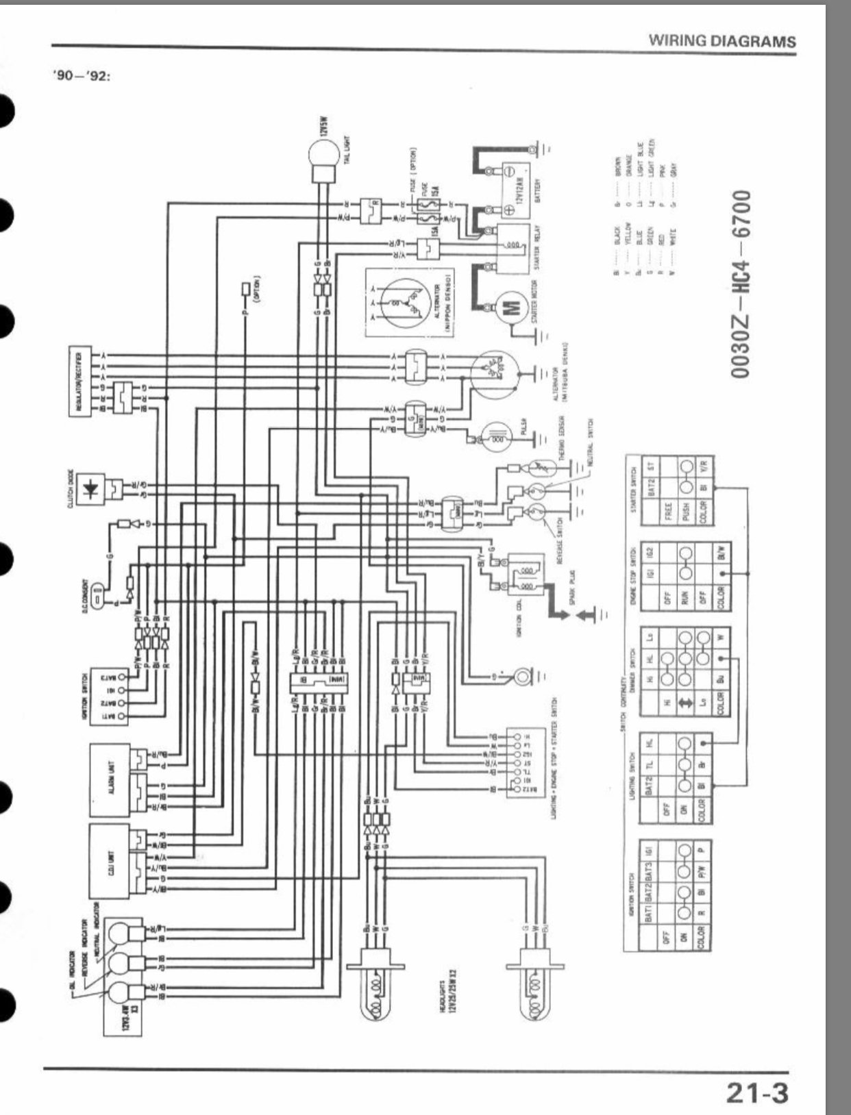
Diagram Klf 300 Wiring Diagram Full Version Hd Quality Wiring Diagram Avdiagrams Fanofellini It
