Disconnect the motor wiring. Jacket the actuators input wiring with UL listed flexible conduit.
Motorized Damper Actuator Wiring Diagram - If you're searching for picture and video information linked to the key word you have come to pay a visit to the ideal blog. Our site gives you suggestions for seeing the maximum quality video and picture content, hunt and locate more informative video articles and graphics that match your interests. comprises one of thousands of movie collections from several sources, particularly Youtube, therefore we recommend this movie for you to view. It is also possible to contribute to supporting this website by sharing videos and images that you like on this site on your social networking accounts such as Facebook and Instagram or educate your closest friends share your experiences concerning the ease of access to downloads and the information that you get on this website. This blog is for them to stop by this site.
Wazipoint Engineering Science Technology How Economizer Works In Centrifugal Chiller Refrigeration And Air Conditioning Energy Saving Devices Save Energy
Detailed on pages 3-4 Example fully addressable panel and DID shown wwwbsb-damperscouk 1 Fire and Smoke Control Systems Regulations and Standards 2 Standard Electro Mechanical Control and Monitoring System.

Motorized damper actuator wiring diagram. The nominal factory setting for Auxiliary. 3 and 4 wiring diagrams. The available sizes are 4 6 7 8 9 10 12 14 16-18-20.
MS Actuator Dimensions in. Ensure damper blade is in the open position with the set. WIRING DIAGRAM 2 Switch.
A wiring diagram is a streamlined conventional photographic depiction of an electrical circuit. Slide the motor and the motor couplings back onto the blade shaft. The wiring diagram right shows the standard connections for all Johnson type actuators.
Use color codes instead. Motorized damper is 4 cfmft2 see Table from ASHRAE Standard California Title 24 edition section states that the dampers shall be certified in accordance with AMCA Publication to have a maximum leakage of 10 cfmft 2 at 1 in. SRD03 FLOATING DAMPER ACTUATOR DESCRIPTION SRD03 floating damper actuator uses bi-directional AC motor.
This video is part of the heating and cooling series o. 3 Actuators may also be powered by 24 VDC. This one covers how to wire the fresh air damper for a furnace without the air conditioner coming on.
Volts Hz Watts VA Rating. It is compact small volume smart design and has high IP class and various torques. Operation A continuous 0 to 10 Vdc signal from a controller to wire 8 Y operates the damper actuator.
Ensure the damper blades are in tightly closed position. Multiple ARD can be wired in parallel. Input No Load Timing Sec180 Rated Torque Lb-in.
Actuator Descriptions Code Number Input Damper Area M9182A120 120 VAC 71 sq ft 74 sq m M9182A24 24 VAC 71 sq ft 74 sq m 2 Electric Smoke Damper Actuators Product Bulletin. See standard actuator part nu mber wiring diagrams for wiring terminations. Compression against damper gaskets for tight shut-off.
Monitoring properties damper actuators will be connected to site wiring when installed by the contractor to provide the relevant functions. N-m Nominal Damperc Area Sq. September 3 2018.
Actuators with appliance cables are numbered. It is widely used for damper control in air-conditioning system and angular travel control and zone valve control in water circuit. Mm Wiring L1 L2 120 VAC 24 VAC L1 Bla L2 Red Black ck White Figure 6.
For further details or full wiring details for other actuator types please contact Advanced Air Sales. Changing a Motor 1. The angle of rotation is proportional to the control signal.
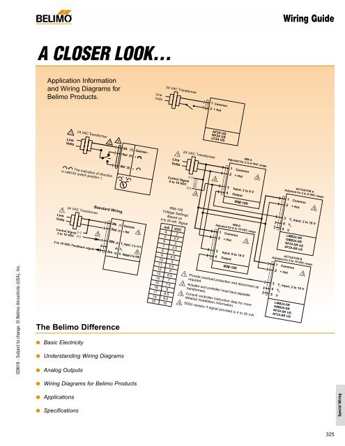
If you are planing to replace the zone controller with SmartZone this diagram is NOT necessary. Wiring for Damper Actuators and Control Valves OnOff Spring Return 24V Blk 1 Common Red 2 Hot 24 VAC Transformer Line Volts 2 3 5 Actuators with plenum rated cable do not have numbers on wires. Screw in conduit connector.
Variety of fire smoke damper wiring diagram. The motor is a 3 wire hook-up with a common a power open leg and a power closed leg. Wiring a Motor See Fig.
Push the UL listed conduit fitting device over the actuators cable to butt against the enclosure. 2550 type dampers with electrical actuators are supplied to site with the flying leads of the actuator coiled up for on-site connection. M6CLOSE M4OPEN M1COMMON.
It reveals the components of the circuit as simplified shapes as well as the power as well as signal links between the tools. Honeywell Damper Wiring Diagram Wiring Diagram Experts Direct coupled actuators spring return models wiring for 02 10 vdc proportioning controller operating multiple actuators wiring for 3 kohm economizer controllers wiring for 3 position economizer controllers override to full open. August 24 2018 by Larry A.
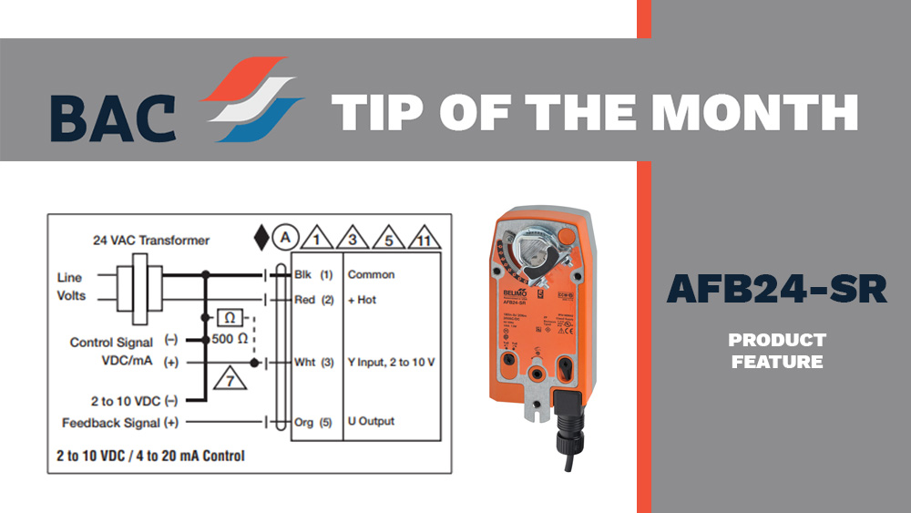
WIRING 120 V AC Wiring Diagrams Auxiliary Switch Wiring Diagram 3900 Dr. Chris Sheehan from Belimo Technical Support team frequently receives questions on how to wire a modulating actuator for onoff. Use the D only on Wiring diagram for D connection to.
When replacing older 5 wire dampers wire as shown and jumper M2M5 terminals on control - panel. Use flexible metal conduit. Loosen the large socket head cap set screw located between the faceplate and the motor coupling.
3 and 4 for motor wiring hookups. Understanding Wiring Diagrams Analog Outputs Wiring Diagrams for Belimo Products Applications Specifications 24 VAC Transformer Line Volts 1 Com mon 2 Hot AF24 US NF24 US LF24 US 24 VAC Transformer 2 to 10 VDC Feedback signal Line Volts Blk 1 Common Red 2 Hot Wht 3 Y 1 Input 2 to 10 V 4 Y 2 Grn 5 Output 2 to 10V Control Signal 2 to 10 VDC Standard Wiring 2 3 1 5 1. It can also be purchased with an S1A end switch as a URD-L no motor or as a URD-LM24 SR-T modulating motor.
M2 c Damper ratings are nominal and based on standard not low leakage dampers at 1 254 mm WC. Static pressure and 2000 FPM 1 0 mlS velocity. Typical VAC Wiring Modulating Table 4.
A 0 to 10 Vdc position feedback output signal is available between wire 9 U and wire 2 G0 to monitor the position of the damper motor. The wiring diagram below shows how to connect the Ecojay Power Damper to an older zone panel that is only designed to work with 2-wire dampers. This is feasible for all SR.
3 Position Air Damper Actuator 220v Electric Air Valve Dirve For Exhuast Air Damper Can Open As 30 60 And 90 Degree Air Conditioner Parts Aliexpress
Msfd Actuator
Belimo Actuator Wiring Guide Industrial Controls
Wiring Guide For Belimo Afb24 Sr How To S Boston Aircontrols
Honeywell Motorised Valve Wiring Diagram For Gif 1024 950 Beauteous S8610u In 1024x931 1024x931 On Honeywell S86 Central Heating Heating Systems Wiring Diagram
Msfd Actuator
General Damper Actuator 4nm 0 10v 4 20ma Modulating For Operation Of Air Control Dampers In Hvac System Adc24v Ac100 240v Air Control Dampers Air Controlactuator Control Module Aliexpress
Pin On Bs
1 Preparation Diagram 2 Wiring Diagram Of Safety Sensor 3 Wiring Download Scientific Diagram


