In bypass the motor is operated directly from. If not the arrangement wont function as it.
Vfd Bypass Wiring Diagram - If you're looking for picture and video information related to the keyword you have come to pay a visit to the right site. Our website provides you with hints for seeing the highest quality video and image content, hunt and locate more informative video articles and graphics that match your interests. includes one of tens of thousands of video collections from several sources, particularly Youtube, therefore we recommend this video that you see. This blog is for them to stop by this website.

Diagram Vfd Bypass Contactor Wiring Diagram Full Version Hd Quality Wiring Diagram Diagramati Mbreporter It
Diagram Vfd Panel Wiring Full Version Hd Quality Jdiagram Fimaanapoli It.
Vfd bypass wiring diagram. Vfd is a short form of variable frequency drive or variable voltage variable frequency drive. Closed the motor is running in bypass from the line input power. Co 5263 Pct Towbar Wiring Diagram Free.
Vfd Bypass Wiring Diagram To properly read a electrical wiring diagram one has to know how the components in the program operate. P4 Non Bypass Mechanical Layout Diagram. VFD BYPASS WITH STAR DELTA STARTER CONTROL WIRING DIAGRAM EXPLAIN - YouTube.
VFD BYPASS WITH STAR DELTA STARTER CONTROL WIRING DIAGRAM EXPLAIN. The VFDs are working based on changing the input frequency and input voltage of the motor we can change the speed of the motor. Monitoring danfoss vfd in bypass october 04.
For the EMB2 a door mounted DriveOFFBypassTest Selector switch is. The VFD with bypass was used to insure there was never an interruption in air flow. P3 Non Bypass Mechanical Layout Diagram.
One of the most common functions of the option panel is to allow switching between VFD control and running in bypass. Standard bypassnon bypass panel is to allow switching between VFD control and running in bypass. In bypass the motor is operated directly from line input power.
P4 Bypass Mechanical Layout Diagram. Vfd Wiring Diagram Showing Power In Out And Control Device Scientific. Power cable as per your size.
Posted by Margaret Byrd Posted on November 2 2018. Wiring diagram for bypass relay car accessories hyundai 7 way pin towbar electrics pct zr2500 universal diagrams 24v to 12v maypole kit smart towing interface tow bar with 5 x 12n socket 12s teb7as true byp full vfd co. In hvac vfds is 2 contactor bypass vfd byp and backups danfoss fc 102 drive with dol changeover circuit diagram true wiring full what the difference between soft should you add a to your three auto.
Vfd Wiring Diagram danfoss vfd wiring diagram vfd bypass wiring diagram vfd control wiring diagram Every electrical arrangement is composed of various different pieces. Option panel instruction manual. For example when a module is powered up also it sends out the signal of 50 percent the voltage in addition to the technician would not know this hed think he provides a challenge as he or she would expect the 12V signal.
See table 12 for their functions. Diagram Vfd Bypass Wiring Full Version Hd Quality Aiddiagram Festivalsportintegrato It. 343 wire size 19 344 wire type rating.
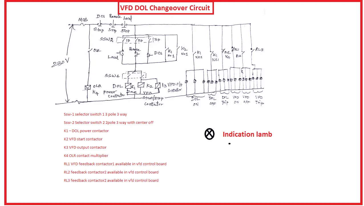
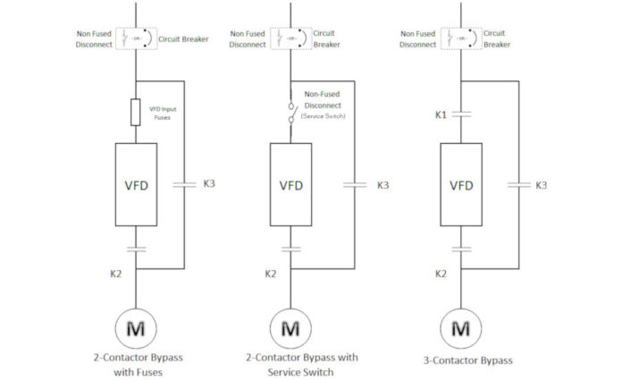
12 Bypass Circuits 121 Three-contactor Bypass The bypass circuit consists of a bypass contactor M3 interlocked with a drive output contactor M2 a drive input contactor M1 and an overload relay. Required Materials to build VFD DOL changeover circuit. P3 Bypass Mechanical Layout Diagram.
Use only copper wire rated for insulation exchange any wires at bottom of circuit breaker exchange any mo wires at output terminals of drive ij2 v2 w2 exchange any motor wires at ol 2t1 4t2 6t3 description wiring diagram bypass project acs550 drive w classic 30hp 460vac n12 djr. Danfoss Vfd Wiring Diagram Wiring Diagram Data Schema Pioneer avic n1 wiring diagram. I am here with giving you a VFD start stop wiring diagram for running a VFD through panel board push button and keypad of the VFD It is called HMI.
Wire and Cable Access 23 Wire Size 24 Wire Type Rating 24. Single Phase Variable Frequency Drive Vfd Circuit Homemade Circuit Variable Frequency Drive For Constant Pressure Water Supply Danfoss Vlt 6000 Bypass Wiring Diagram Wiring Diagram And. A 2-contactor bypass allows a technician to flip the switch bypass the VFD and the motor will resume running at 100 percent speed.
If a VFD fails the motor it controls will stop running completely. Electromechanical bypass EMB electronically controlled bypass ECB The EMB is operated by selector switches on the front of the panel. Vfd Bypass Wiring Diagram.
Both power paths have protection. Dash lines indicate customer installed devices and wiring. VFD Start Stop Wiring Diagram.
In bypass the motor is operated directly from line input power. Push button NC Normally Close. Connector mounting C channel.
If you have not seen a wiring diagram a bypass is most commonly a reversing starter two contactors and an overload where one contactor is connected to the output of the VFD and one contactor is connected to the mains. Eventually the systems should be shut down in order to safely replace the drive. 2 Stop1start1 Push Button NO Normally Open.
2 wp_ad_camp_3 Thermal Over Load Relay 1. China Low 220v Single Phase 0 4 2 2kw Cheap Vfd Suppliers Manufacturers Factory Direct Whole Anyhertz. Diagram Vfd Bypass Wiring Full Version Hd Quality Kdiagram Lavocedelmare It Smart Bypass Relay Teb7as 7 Way Towing And Trailers Ltd Te 7736 Smart Bypass Relay Wiring Diagram.
P2 Bypass Mechanical Layout Diagram 3-8 Figure 36. P5 Bypass Mechanical Layout Diagram. On switching to normal.
1 Vfd 2 Motors. The timing logic must ensure time delays in the switching circuit to ensure that on switching to bypass the line contactor opens first followed by the output contactor opening after a delay of 1 to 2 seconds. A variable frequency drive regulates the speed and operation of an electric motors.
Two types of bypass options are available. P2 Non Bypass Mechanical Layout Diagram. As per your amperes of KVA rating.
Each component should be placed and connected with other parts in particular manner. The bypass DOL starter should then closes after a further delay of 1 to 2 seconds. Danfoss vfd with bypass wiring diagram.
The drive is programmable.

مهندس محمدیان 09132211861 تعمیرات اینورتر اینورتور درایو 3vf Vvvf Vfd Vsd Abb Acs350 Wiring Diagram تعمی Circuit Diagram Inverter Ac Wiring Diagram

Vfd Block Diagram Block Diagram Diagram Inductors
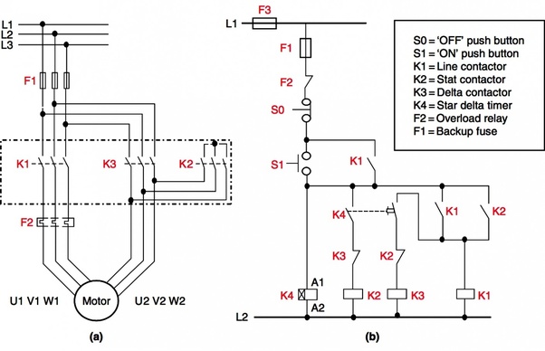
Ecclesbourne Valley Railway News Feed View 20 Star Delta Timer Wiring Diagram
Vfd Dol Changeover Circuit Vfd Bypass Arrangement Electrical4u
Vfd Schematic Diagram And Control Workingmuslimah


Pin On Electronics
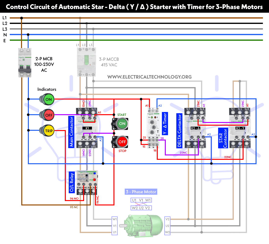
Ecclesbourne Valley Railway News Feed View 20 Star Delta Timer Wiring Diagram

Inverter Standard Wiring Diagram T Power Diagram Floor Plans
