19 Best Glowshift S White Elite 10 Color Series Gauges. Resources installation support instructional downloads misplaced instructions are never a good thing autometer s library of instructions ensures that you.
Digital Boost Gauge Wiring Diagram - If you're looking for video and picture information linked to the keyword you've come to pay a visit to the ideal site. Our site gives you suggestions for viewing the maximum quality video and image content, hunt and locate more enlightening video articles and images that match your interests. includes one of tens of thousands of movie collections from various sources, especially Youtube, so we recommend this video that you view. You can also contribute to supporting this website by sharing videos and graphics that you enjoy on this site on your social media accounts like Facebook and Instagram or tell your closest friends share your experiences about the simplicity of access to downloads and the information that you get on this site. This site is for them to stop by this site.
Glowshift 10 Color Digital Led Boost Vacuum Gauge
Boost gauges can read boost level and many read engine vacuum.

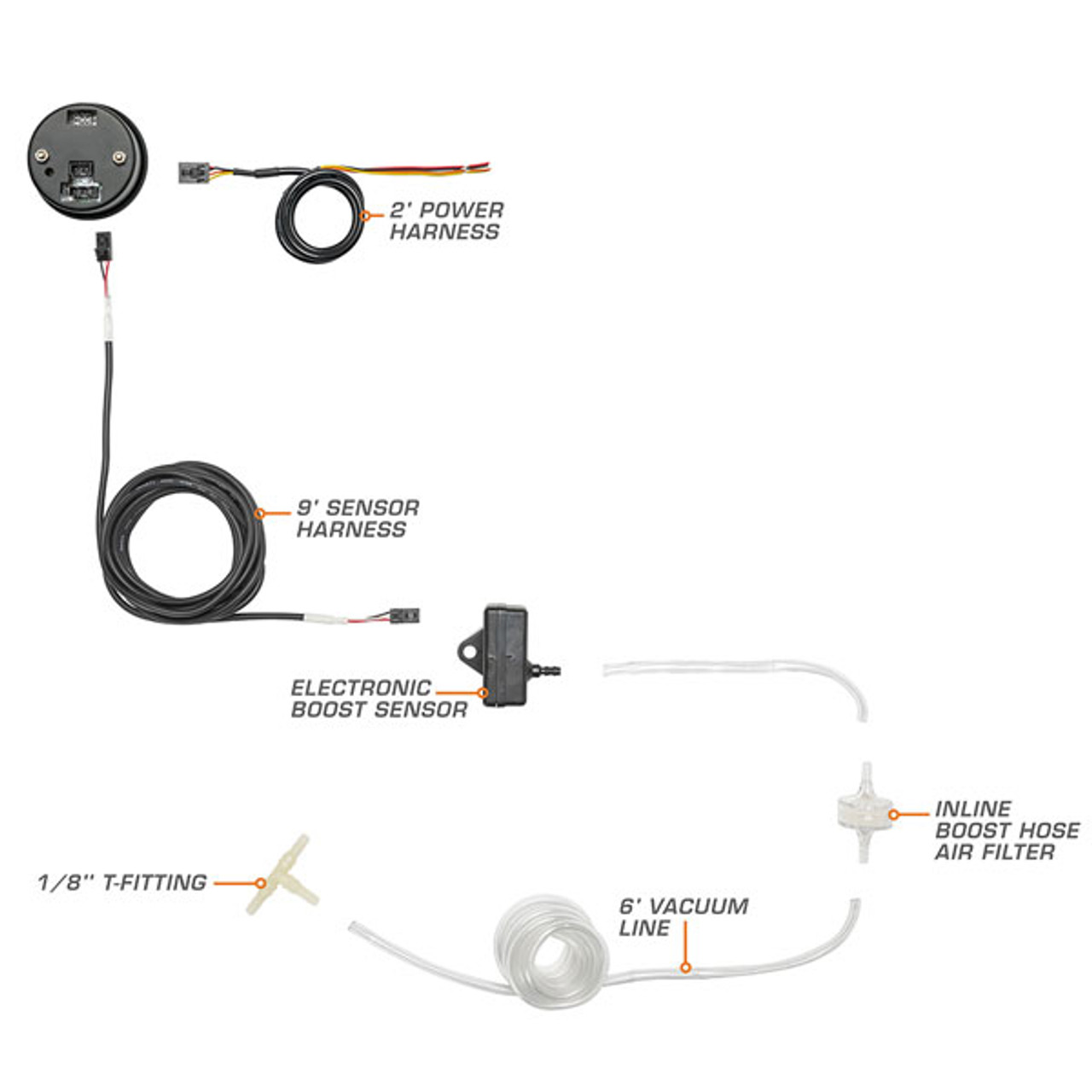
Digital boost gauge wiring diagram. The connection diagram is shown below. In most cases like with the Greddy Electronic Boost Gauge you will get an electronic sending unit that mounts in the engine bay and there will be a wiring harness that runs through the firewall to your gauge instead of a thin vacuumboost line. Dakota digital manufactures digital instrumentation and accessories for the automotive motorcycle and car audio enthusiast.
DO NOT OVER TIGHTEN ADAPTER FITTING OR GAUGE MAY BE DAMAGED. If so do you still happen have the wiring diagrams. In order to test for power reconnect the Negative Battery Terminal.
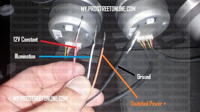
Most vehicles break the electrical connection to accessories while the engine is being started. Using a Test Light locate a Constant 12-volt Power. Mount the gauge and secure with the included mounting.
Fuel Pressure Exhaust Gas Temp. Prosport Gauge Wiring. There is one right off of the intake manifold near the throttle body but its 12 inch in diameter and Im having absolutely no luck finding a tee that goes from 12 inch to the size needed for the boost gauge solenoid AEM Digital Boost Gauge which is 14 inch.
Slide the BoostVacuum Line onto the back of the Gauge and secure the supplied clamp. Auto gauge boost gauge wiring diagram another graphic. Variety of glowshift boost gauge wiring diagram.
Insert the bulb into the lamp socket. Connect the red power wire to a switched 12 volt source that maintains power during engine cranking. Boost Temperature Gauge Download PDF.
Boost Gauge Png Images Pngwing Diagram Wiring Sdo Cs1 Full Version Hd Quality Aidiagram Concorsieselezioni It Bb 9539 Boost Gauge Wiring Diagram On Digital Dragon Schematic. I have a boost gauge and. Diagram rite temp wiring for rpm gauge wire full fuse box 2006 le613 mack ford temperature 1969 corvette vw new vdo question water electric blue circuit how to install auto meter sport comp ii digital sdometer 2 prosport boost 98 toyota avalon o2 sensor installation instructions fuel.
Glowshift Boost Gauge Wiring Diagram Luxury Luxury Sunpro Temp Gauge. Digital gauge wiring diagram. Select the desired mounting location of the instrument.
It may be necessary to remove Vehicle Trim andor Kick Panels in order to gain access to the vehicles Fuse Box. Pressure or VacuumBoost Gauge 1 Lamp socket 1 Light Bulb 1 VDO Mounting bracket from assembly or wiring diagram. Diagram Yamaha Digital Gauge Wiring Diagram Full Version Hd I am looking for wiring diagrams for ignition and gauges for all of the yamaha digital display multi function gauges operate the same.
Twist in light socket assembly and connect one wire to dash lighting circuit or other 12V power source and the other wire to a good ground. Diagram Fuel Pump Relay Switch Wiring Full Version Hd Quality Thediagramguru Patriziaprestipino It. If you dont have the relay module the gauge connects like in the picture below.
I bought 3 electronic gauges boost egt oil pressure. A wiring diagram is a simplified standard photographic representation of an electric circuit. Voltmeter gauge wiring diagram wiring diagram is a simplified customary pictorial representation of an electrical circuitit shows the components of the circuit as simplified shapes and the facility and signal contacts with the devices.
If you have a turbocharged engine installing a boost gauge is a great modification. Select the location where you will mount the gauge and mark a center point and cut a 2 16 hole 52mm. I have the instructions but im not real sure where to tap in for acc 12v ignition switch.
Assortment of glowshift boost gauge wiring diagram. Connect the nylon line to your boost gauge or if you have an electronic boost gauge connect the wiring harness to the boost or pressure solenoid and run the electrical connector into the cabin as you would have the nylon line. The tee needed for that would have to be 12 to 12 to 14.
Youll likely have GND 12VDC IGN and backlight wires or something similar. The gauges backlight will stay ON the all time unless you remove the power to the Pro-Gauge controller or add a switch to the 12V wire that connects to the 12V terminal of the Pro-Gauge. Any help with this would be amazing.
Now well move onto the wiring part of How To Install a Boost Gauge. Wire gauge diagram blog wiring diagram saas turbo diesel boost 0 30psi gauge white dial face 52mm 2019 hot 2 inch 52mm turbo boost vacuum gauge 12v blue red led. Route the tube from the gauge to the engine.
If the boost gauge is connected to one of these circuits the auto zero function will not work properly and inaccurate readings will result. E Support Car 2 52mm Digital Turbo Boost Gauge Red LED. Boost - Mechanical Electrical Oil Pressure Oil Temperature Water Temperature.
Otherwise the structure wont work as it should be. Click on the image to enlarge and then save it to your computer by right clicking on the image. Hookup Wiring the Gauge Illustration A.
PRESSURE VACUUM BOOST GAUGES NOTE. Snap the socket into the socket hole on the back of the gauge. Pressure Temperature Gauge Air Fuel Ratio Boost Vacuum Download PDF.
It reveals the parts of the circuit as simplified shapes as well as the power and also signal links between the devices.
How To Install Defi Boost Gauge My Pro Street
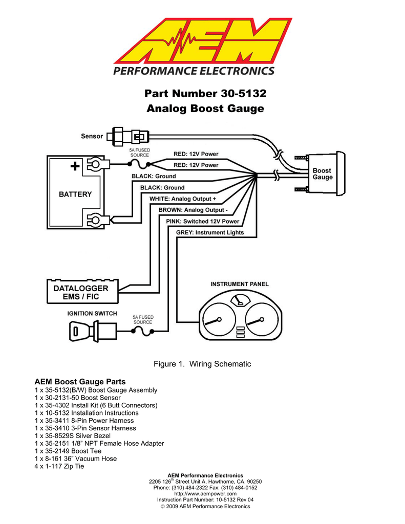
Aem 30 5132 30 5132m Instructions Manualzz

Audizine Forums
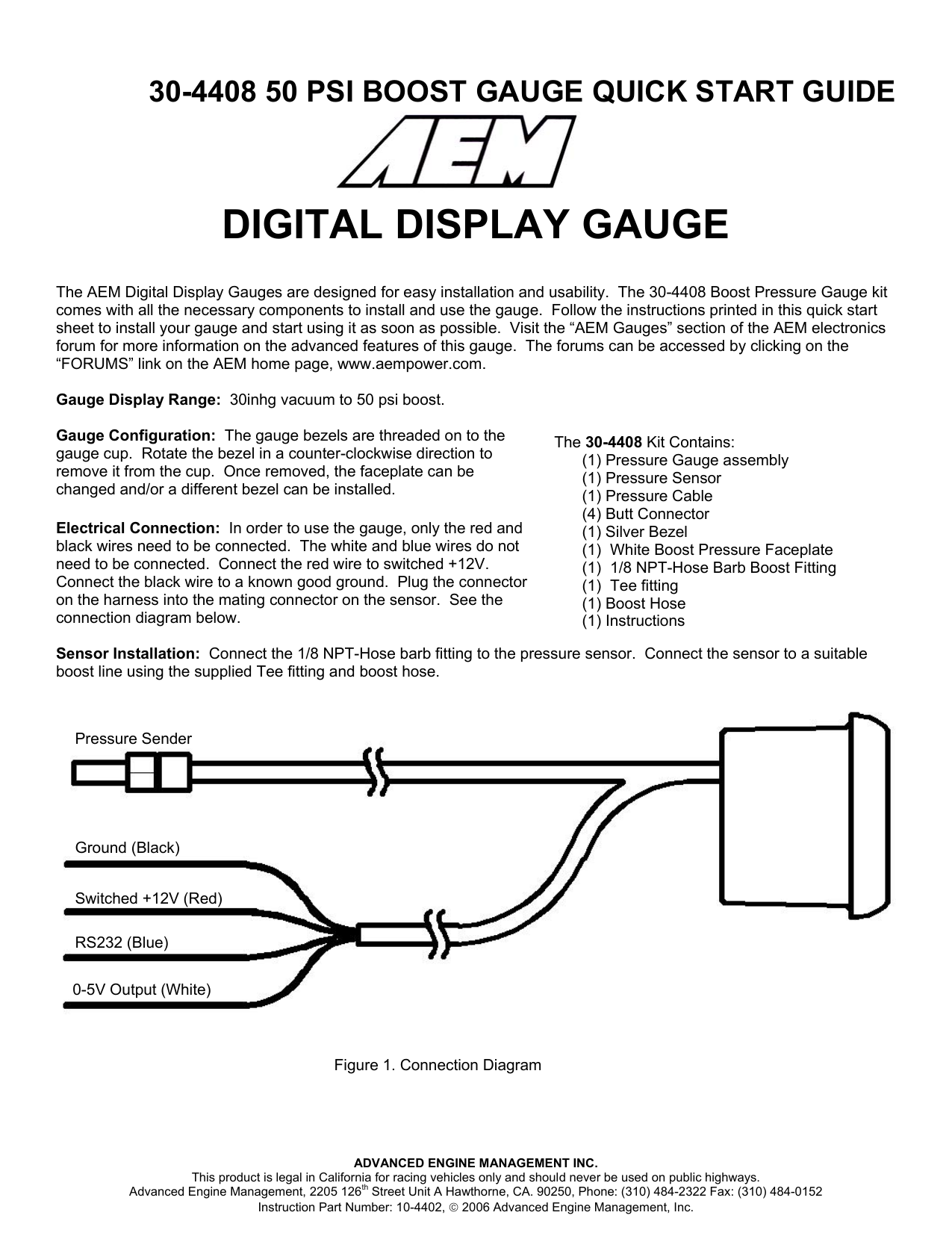
Aem 30 4408 Instructions Manualzz

3 In 1 Lcd Gauge Instructions Autotecnica

New 2 52mm Evo Lcd 7 Colors Car Turbo Boost Gauge Universal Digital Car Boost Meter Psi With Sensor Car Meter Tt100110 Psy Psi Meterpsi Gauge Aliexpress

Wiring Diagram Gauge Schematic Electrical Wires Cable Png 960x1242px Wiring Diagram Area Black And White

Trax Gauge Instructions Sg611240 Fixed Machines Components
Digitl Boost Gauge Wiring Diagram Doesnt Make Sense Focus Fanatics Forum
