Click on the image to enlarge and then save it to your computer by right clicking on the image. The Override Key Switch is designed to be installed in a secure location outside wired in parallel or series with the power supply and the electromagnetic lock EM lock.
Override Key Switch Wiring Diagram - If you're searching for picture and video information related to the keyword you've come to pay a visit to the ideal blog. Our website gives you hints for viewing the maximum quality video and image content, search and locate more enlightening video articles and images that fit your interests. comprises one of tens of thousands of movie collections from various sources, particularly Youtube, therefore we recommend this movie that you see. This site is for them to visit this site.
Starter Ignition Switch Bypass Circuit Question Ih8mud Forum
Wiring Diagram Detection Circuit with Key Removed GREEN LED EOL DEVICE PN 83-132487-200 NO.

Override key switch wiring diagram. Take 1 normal 2 way 1 gang light switch. I dont know whats that all about. Variety of scooter ignition switch wiring diagram.
Screw the switch in place. Ive been having a look at this wiring diagram and i understand the function of the overide switch but i am not sure about how the emergency key switch is wired in this diagram. Is the diagram wrong.
Go back under the hood and reconnect the red 12V cable to the battery. How to wire a lawn mower ignition switch. That is a good tip and will impress your assessor.
Diagram in pictures database override switch wiring diagram just download or read wiring diagram. If orange is tied to orangewhite then orange comes in fuse box out through fuse 4 on orangeyellow and onto relay coil which closes relay - then even when the kill switch is opened the orangeblack keeps power on the coil through the closed contact of the relay and so current flows back other way through. Refer to the installation wiring diagram for detailed wiring connec-tions.
When switch is in off position Light will be fed from photocell. The key can only be removed in the armed position. Orangewhite is hot when kill switch closed - that starts the sequence that sets the latch.
WIRING DIAGRAMS Figure 1 and Figure 2 show wiring diagrams for the Key Maintenance Bypass Switch. Its pretty easy. Done within the switch back box containing the.
Connect it as a one way switch ACROSS THE STRAPPERS -. The Key Maintenance Bypass Switch provides a means to short the Metron Actuator circuit leads for safe disconnec-tion of conventional and addressable control units. Attach that wire to the grounding point you found in step 27.
Connect the switch to ground. Repeat steps 1 through 4 two more period for a include of 3 cycles30 minutes. Nothing here should be confused with the latest generation of PWM VARIABLE SPEED CONTROLLERS which have much higher.
This will have 3 terminals normally Com L1 L2. Intermediate and the over-ride. Evinrude ignition switch wiring diagram Omc Key Switch Wiring Diagram Evinrude Ignition Switch Wiring Diagram In 88 89 110 Jpg.
Now connect the wire coming in from the engine bay to the connection on your switch and connect the wire with the resistor on it to the - and load connections on the switch. Wire the magneto to the switch. If you look at the wiring diagram you download it off this site on the left side of the bike there is a small plug I think its red jump those 2 wires.
Connect the switch to the Solenoid. The vehicle is now ready to relearn the Passlock Sensor Data Code andor passwords vis-Ð-vis the adjacent ignition switch transition from OFF to CRANK. Connect your feed to the light to the com Perm Live to L1 Sw Live from Photocell to L2.
Wiring Diagram for Push button Start Save Universal Ignition Switch Wiring Diagram Jerrysmasterkeyforyouand pccmotor 2010 10 tire 150cc 200cc 250cc kazuma roketa taotao atv 4 wheeler go kart tr55 258 12 tire 150cc 200cc 250cc kazuma roketa taotao atv 4 wheeler go kart tr58. 99 of people wire the key switch. So litterally 2 3 pieces of cable and all wiring.
Ive done this to every R6 Ive owned 4. Obtain a circuit diagram. Abs vsc traction control override.
Wiring Diagram Release Circuit with Key Removed Figure 2. Scooter ignition switch wiring diagram Moped Engine Diagram Lovely Scooter Cdi Wiring Diagram Moped Ignition Switch New Free Download. Connect the accessories lights.
Ignition Switch Connector Kzrider Forum Kz Z1 Z Motorcycle Enthusiast S. Ignition Switch Wiring Passlock Bypass Diagram. Remote controlled light switch -- retrofit with manual override and no extra writing.
Locate all components that need wiring. More wiring diagrams you read more knowledge you get and more chances to always love reading wiring diagrams. Ignition switch wiring diagram data freightliner harley davidson dorman how to wire a motorcycle basic remove the keyed ac tao full universal scooter security 3 position 6 mopar murray 42544x8c 4 way engine kill for motorcycles bypass key suzuki volusia forum pin starter connector kzrider ezgo buzzer john deere.
Ups bypass switch wiring diagram Static bypass Switch Circuit Diagram Inspirational Alternating Relay Wiring Diagram New attractive Led Lighting Circuit. Switch the switch on and it. Tilt twist OFF the ignition and wait 5 seconds.
Because of this reason reading wiring diagram should be started from earlier. Then if you connect the power wires from the ignition to a switch it should work. It is as what you can obtain from the wiring diagram trying to bypass security system key switch wire broke used resistors in big connector worked for a.
These diagrams show the use of relays ONOFF sensors ONOFF switches and ONOFF fan controllers. Two LEDS indicate SYSTEM ARMED or SYSTEM INACTIVE when the key is inserted and turned. METRON SYSTEM ARMED THE KEY CAN BE REMOVED TO SUPERVISORY.
Optional override switch turns on fan by-passing temp sensor and AC relay. Provide voltage by connecting the battery. If the EM lock malfunctions due to the failure of the reader or other reasons the user can switch between normally closed NC and normally open NO contacts by using the key thus forcing the door to open.
Surely the neutral should not be wired into the switch but the line at the light instead.

Bypass Ford Ignition Switch Wiring Diagram Google Search In 2021 Ignition Switch Wiring Diagram Wiring Diagram Ignite
Rc51 Ignition Switch Bypass
Your Friend And My Friend Securitron Mk Key Override Youtube

Security Vulnerabilities Created By Key Switches

Push Button Ignition Switch Wiring Diagram New Ignition Switch Wiring Diagram Boat Wiring Trailer Wiring Diagram

17 Motorcycle Ignition Switch Wiring Diagram Motorcycle Diagram Wiringg Net Kill Switch Electrical Diagram Wiring Diagram

15 Small Engine Starter Generator Wiring Diagram Engine Diagram Wiringg Net Wiring Diagram Electrical Diagram Electrical Wiring Diagram

Ignition Kill Switch Wiring Schematic And Wiring Diagram Kill Switch Motorcycle Wiring Wiring Diagram
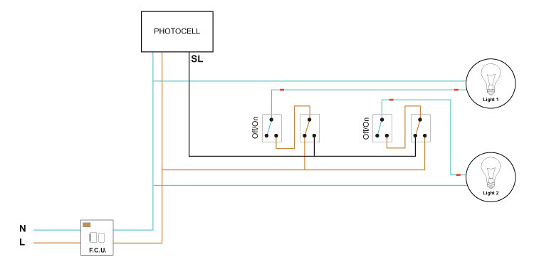
Photocell Override Will This Circuit Be Ok Diynot Forums
