If unit wiring diagram is not available or Low ambient pressure switch S11 is wired in series with does not show the low ambient kit refer to appropriate outdoor fan relay or compressor contactor single-stage wiring diagram in figures 3 through 13 for. When plugged in the controls become an integral part of the unit wiring.
Lennox Low Ambient Kit Wiring Diagram - If you're looking for picture and video information related to the key word you've come to pay a visit to the ideal site. Our website gives you hints for viewing the highest quality video and image content, hunt and find more enlightening video content and images that fit your interests. comprises one of tens of thousands of movie collections from various sources, particularly Youtube, therefore we recommend this video that you see. You can also contribute to supporting this site by sharing videos and graphics that you like on this blog on your social media accounts like Facebook and Instagram or tell your closest friends share your experiences about the simplicity of access to downloads and the information you get on this site. This site is for them to stop by this site.
Lennox Air Conditioner Heat Pump Outside Unit Manual L0805504
Refer to figure 4 for field wiring diagram.

Lennox low ambient kit wiring diagram. It should not be. 2 and wire lowambient pressure switch as follows. Lennox A2CWKT01LM1 Low Ambient Control 6-75 Ton.
NOTE A complete unit wiring diagram is located in side the unit control box cover. See Controls section and Lennox Price Book for additional thermostats. After change Dip SW setting press reset switch to reflect the setting.
Low Ambient Kit for use with expansion valve systems only LB57113BC 24H77. For 480600 volts application connect the power supply leads to the 480600 VAC terminal. The low ambient kit is pre-set at the factory and re-quires no further adjustment.
Each input and output on the module shall be clearly marked with the wiring diagram key number. Lennox Low Ambient Kit Wiring Diagram Installation Instructions Tga Tca180 Tga Tca210 Manualzz. Once the Kit is installed use wire ties to dress the wires so they follow the current wire bundle.
Low Ambient Kit Goodman Daikin Lakt01. 3 Install room thermostat ordered separately on an in-side wall approximately in the center of the conditioned area and 5 feet 15 m from the floor. Control options such as econo mizer warm up kit Honeywell W973 control or Honeywell W7400 control connect to the unit with jackplugs.
Connect the other black wire from the solid state relay to the contactor terminal T2 from where the black fan motor lead was disconnected. With minimum field wiring. Low Ambient Kit Air conditioning units will operate satisfactorily down to 45 F 7 C outdoor air temperature without any additional controls.
Matched according to Lennox recommendations for the com pressor to be covered under warranty. Low Ambient York Central Tech Talk. 8- Place the wiring diagram provided in this kit on the inside of the control door.
Commercial units are also equipped with a low volt age terminal strip to facilitate thermostat field wiring. NOTE A complete unit wiring diagram is located in side the unit control box cover. Low Ambient Kit -- ZGZCZH 036-150 A B Box 3 - 12-12 ton Raider NOVAR 2024 DDC Kit 86W93 and 86W94 NOVAR 3051 DDC Installation Kit 19F75.
Tubing 93G35 58 in. 3 Install room thermostat ordered separately on an in. 6- Install the kit power wiring harness as shown in figure 6.
Compressor Hard Start Kit 10J42 81J69 Compressor Low Ambient CutOff 45F08 Freezestat 38 in. Connect the blue lead from the low ambient pressure switch to the same NC terminal of the isolation relay. Lennox Controls And Hvac Accessories Manual L0806307.
Connect the 3-pin wire assembly to J5 on the control board 3-pin male connector. Wiring diagrams If unit wiring diagram is not available or does not show the low ambient kit refer to appropriate wiring diagram in figures 3 through 13 for wiring. Page 3 Low ambient kits are shown with optional arrows on unit WIRING wiring diagrams.
Connect a wire from the outdoor fan relay terminal number 3 to the other NC terminal of isolation relay. We have chosen a plant within your. Tubing 50A93 Indoor Blower Off Delay Relay 58M81 Low Ambient Kit 68M04 Monitor Kit Service Light 76F53 Outdoor Thermostat Kit Thermostat 56A87 Mounting Box US 31461 Refrigerant Line Sets L156515.
1 - Controller Module 1 - Liquid Line Temperature Sensor 1 - Outdoor Air Temperature Sensor 1 - B Y O Low Voltage Wiring Harness 1 - Sensor Clamp 1 - Thermal Grease 1 - Insulation Tape 1 - Information Label 3 - Screws Wire Nuts Wire Ties 1 - Installers Guide. K1 is energized by the indoor thermostat. The kit also includes a wiring harness mounting bracket and includes an IO Module Kit C0CTRL01AE1L.
Using SW101 SW102 You can use Low Ambient Kit Mode Set Low Ambient Kit Operation L1 ON 2 3 4 L1 ON 2 SW102 SW101 Notes Default status is all off. 24V Class II circuit connections are made in the low voltage junction box. INSTALLATION INSTRUCTIONS LowAmbient Pressure Switch 482 01 5120 00 3 PROCEDURE 1 WIRING FOR ALL VOLTAGES OF AIR CONDITIONERS For all voltages of air conditioners refer to Fig.
16F18 ModelPart. CAUTION If the Dip SW is set IO module System is operating preferentially than outdoor unit setting. A Wiring diagrams show the controller connection for 120 277 volts supply.
Disconnect black fan lead from contactor and connect this lead to yellow or violet wire from lowambient. Need your unit today. Crankcase heater and a freezestat should be.
The quantity you requested is not available at your chosen plant. See wiring diagrams for specific units. Low Ambient Control Kit Model 2la04700824 Manualzz.
This wire has a sleeved 14 male tab for attaching to the fan motor wire terminal. Low Ambient Control Kit BAYLOAM103 HDPC-IN-18B 18-HE46D1-3 LOW AMBIENT KIT CONTENT. Hvac Defrost Wiring Connection Diagram Wiring Diagram.
Lennox Low Ambient Kit Wiring Diagram 2scu13 A I R C O N D I. 7- Bundle wiring and use wire ties to route wiring away from sharp edges. 5- Disconnect P87 from J87.
Discard P87 and associated wiring. Lennox Low Ambient Kit Wiring Diagram Servicemanualcha16 953to2753 Manualzz. See product availability listed below visit Commercial Quick Quote or call the Rapid Replacement Hotline at 1-800-4LENNOX.
Refer to figure 4 for high voltage field wiring diagram. Altering the setting may greatly reduce. 9- Close unit panels and restore power.
Refer to the Engineer. Condenser Fan Cycling Controls Hvac Training Solutions. Kit can be added in the field enabling unit to operate properly down to 30 F 1 C.
The module shall provide user adjustable low ambient control so that the unit can operate down to 0F as standard by staging the condenser fans. Wiring Diagram 0140L01008 - use with AC units.
Lennox Ahu Heat Pump Honeywell T Stat Wiring Doityourself Com Community Forums
Lennox Controls And Hvac Accessories Manual L0806301
G20re Series Manualzz
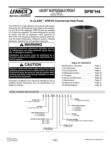
Lennox Spb Manualzz
Lennox Controls And Hvac Accessories Manual L0806301
Lennox Air Conditioner Heat Pump Outside Unit Manual L0806422
I Have A Lennox Hp26 036 7p Heat Pump In Cooling Mode The Unit Intermittently Runs Correctly But Then At Times Runs For
Lennox Controls And Hvac Accessories Manual L0806307
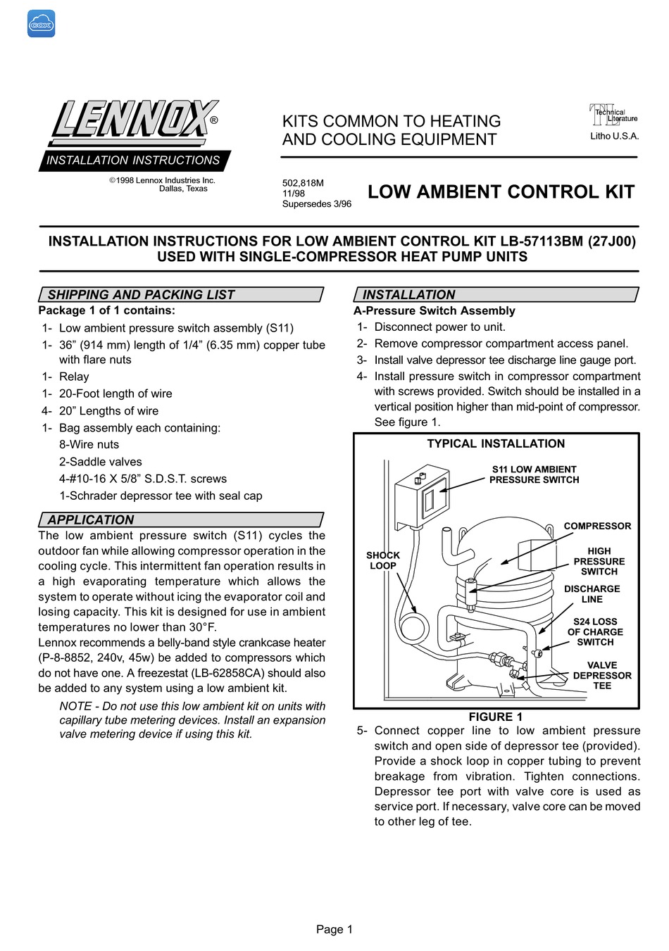
Lennox Lb57113bm Installation Insrtuctions Pdf Download Manualslib


