The Apollo SA4700-102 is an addressable intelligent input output interface module. High Level input output 3.
Apollo Input Output Unit Wiring Diagram - If you're searching for picture and video information related to the key word you've come to pay a visit to the right blog. Our website provides you with hints for viewing the maximum quality video and image content, search and find more enlightening video content and images that match your interests. includes one of thousands of movie collections from several sources, especially Youtube, therefore we recommend this movie that you see. This blog is for them to visit this website.

Intelligent Input Output Unit Installation Guide Manualzz
Audio can be routed to these outputs via the cue mix routing in Console accessed via the Cue Outputs popover.

Apollo input output unit wiring diagram. Maximum Current Consumption at 24V. Field Device Output Ground Input Common DL405 System DC Output DC pwr sourcing sinking Power sinking pull-up Supply R Rinput NOTE 1. Wiring Diagram Images Detail.
If the LED is on the output is activated. Output Btuh 22 500 30 50 000 input 19 28 700 37 500 38 900 50 900 62 50 000 117 84 110 583 147. 22 to 40V DC.
203 - Magnetic lock connection 23. The inputoutput and ground terminals on the TurboCharger will accept 8 to 3 AWG wire. 67 - 3500 3600 Wiring Right hinged gate 12.
Connection 16 112 - Magnetic lock connection 16 113 - Guard station 16 114 - Exit and edge inputs wiring. Use a minimum of 8 AWG conductors rated for at least 75 º C. Ergonomic design for ease of wiring and faster installation.
204 - Guard station connection 23. It can report fault switch open and switch closed levels. Apollo Twin When Apollo Twin is used as an expander unit the Line 34 outputs of the Apollo Twin do not appear in the Core Audio driver.
19 - SOLAR PANEL CHART. EN 54-17 EN 54-18 Certified. 63 - 416 816 Actuator wiring Push to open 10.
Click Here To Enquire About This Product Now. When digital clipping occurs in input when. Suitable for semi flush or surface mounting.
- 416 816 Actuator wiring Standard 10. The Apollo 40 S has a fixed output of kW 40 000 Btuh The Apollo 1530 S and 3050 S are factory set to the maximum Output. 65 - T5 T7 H12 M12 Wiring Push to open 11.
Switch input closed LED disabled. OUTPUT INPUT HIGH POWER VENTED ENCLOSURE L T V R RTB80A 400WATTS RCAMP3 INPUT WIRING RTB80A FEATURES HIGH LEVEL INPUT From head unit RCA output From any device with a 35mm output 1. Inputs in Console can be directly routed via Output Route menu only to hardware outputs of the same unit.
Input or output metering is selected with the METER switch 19 and the inputoutput state is shown by the METER indicators 15. 68 - 7200 Wiring 13. The Intelligent InputOutput Module is used to monitor single pole volt free contact inputs and control relay output contacts.
The lugs are rated to accept a single conductor. 21 - INSPECTION AND OPERATION. Wiring diagrams Fault finding guide.
55mA 22 to 40V DC. One volt-free single pole changeover relay rated at 1A 30V DC or 03A 12 V AC. Apollo XP95 Input Output Unit with Isolator 55000-847APO.
Inputs in Console can be directly routed via Output Route menu only to hardware outputs of the same unit. 205 - Exit and edge inputs wiring diagram 24. 9 - ACCESSORY INPUTS AND OUTPUTS 13 91 - Outputs 13 92 - Inputs 13 93 - Communication buses 14 94 - Programming the plug-in receiver and remote controls 14 10 - WIRING AND CONNECTIONS 15 11 - OPTIONAL INPUTS 16 111 - Fire dept.
This unit is designed for use on Apollo protocol analogue addressable fire alarm loop circuits. Connect directly to your head units RCA ouputs. THIS IS THE SYMBOL FOR GROUND.
Switch input closed LED on. Apollo Twin Designating Apollo Twin as the monitor unit is not a recommend configuration. 202 - Fail safe connection 23.
Meets BS 7273-4 failsafe requirements. 201 - Fire input 23. DO NOT attempt to drive a heavy load 25 mA with this pull-up method NOTE 2.
If the outputs being used are using the voltage supply from Apollo III each output. The common C1 is for outputs Y0-Y3 and C2 is for Y4-Y7. The Input Output Unit provides a voltage-free double pole changeover DPCO relay output a single monitored switch input and an unmonitored non-polarised input.
20 - OPTIONAL INPUTS. The dB values of the meter LEDs are indicated between the meters for channels 4 and 5. Wwwapollo-firecouk 4 1 XP95 InputOutput Unit Installation Guide General The XP95 InputOutput Unit part no 55000-818 is supplied with a backbox for surface mounting.
See wiring diagram for proper set up. Incorporates the functions of a switch monitor zone monitor and output unit in one device. Apollo gate opener wiring diagram Wiring Diagram For Electric Gate Motor New Apollo Gate Opener Wiring.
Operating Temperature-20C to 70C. 64 - T5 T7 H12 M12 Wiring Standard 11. Route the wiring bundle as appropriate.
Apollo Fire Detectors Limited 36 Brookside Road Havant Hants PO9 1JR UK Tel 44 023 9249 2412 Fax 44 023 9249 2754 Email. 206 - Radio receiver connection third party 24 207 - Optional power output 24. When Apollo Twin unit is used as an expander unit the Line 34 outputs of the Apollo Twin do not appear in the Core Audio driver.
69 - 7300 Wiring 14. Apollo SA4700-102 Intelligent Input Output Interface Module. When using an Apollo Twin unit cue mixes can be routed to the Line 34 outputs of that unit as well.
18 - 120VAC WIRING AND CONNECTIONS. 66 - 3500 3600 Wiring Left hinged gate 12. Using the pull-up resistor to implement a sourcing output has the effect of inverting the output point logic.
Power input speaker or headphone output microphone input an antenna EQUIPMENT MOUNTING Once the cable assemblies have been made attach the 15 pin dsub and coaxial cable connectors to the rear connector mounting plate and the mounting frame as illustrated in Figure 2 and Figure 3. Each common can take 7-48VDC. There are two separate commons for the outputs.
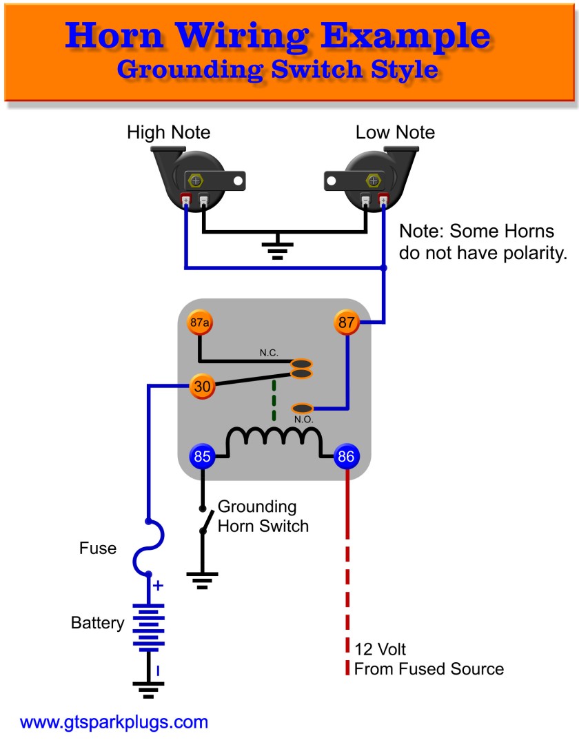
Diagram Tj Horn Wiring Diagram Full Version Hd Quality Wiring Diagram Avdiagrams Fanofellini It

Cat 3126 Ecm Wiring Diagrams Caterpillar Ecm Catecm Wiring Diagram Diagram Wire

Diagram Delta Plc Wiring Diagram Full Version Hd Quality Wiring Diagram Avdiagrams Fanofellini It

Scosche Output Converter Wiring Diagram 3 Phase Converter Alarmas Para Autos Alarmas Autos

Inverter Wiring Diagram For House Wiring Diagram Database Alt Image

Rs232 To Usb Wiring Diagram Usb Console Cable For 3012 Blade Center Switch Module Lan Switching And Routing C Serial Port Usb Cable Wiring Usb Wiring Diagram
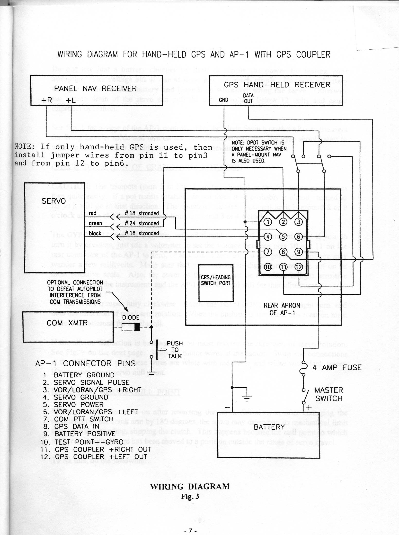
Diagram Renault 11 Wiring Diagram Full Version Hd Quality Wiring Diagram Avdiagrams Fanofellini It
Flow Switch Wiring Diagram Wiring Diagram Diagram Electronic Circuit Projects
Diagram 2013 Yukon Wiring Diagram Full Version Hd Quality Wiring Diagram Avdiagrams Fanofellini It
