A wiring diagram is a sort of. Iota Emergency Ballast Wiring Diagram 1991 Ford Explorer Fuel Pump Bege.
Led Emergency Ballast Wiring Diagram - If you're looking for video and picture information related to the keyword you have come to visit the ideal site. Our website provides you with hints for seeing the maximum quality video and image content, hunt and find more enlightening video articles and images that fit your interests. comprises one of tens of thousands of video collections from several sources, especially Youtube, therefore we recommend this movie for you to see. This site is for them to stop by this website.
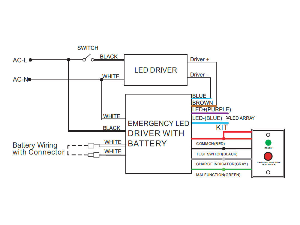
How Are The Emergency Led Drivers Work
It reveals the components of the circuit as simplified shapes and the power and also signal connections between the tools.

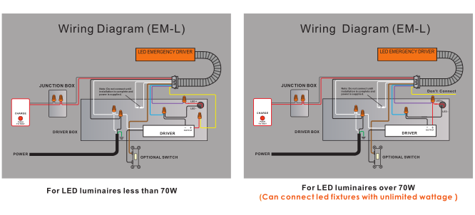
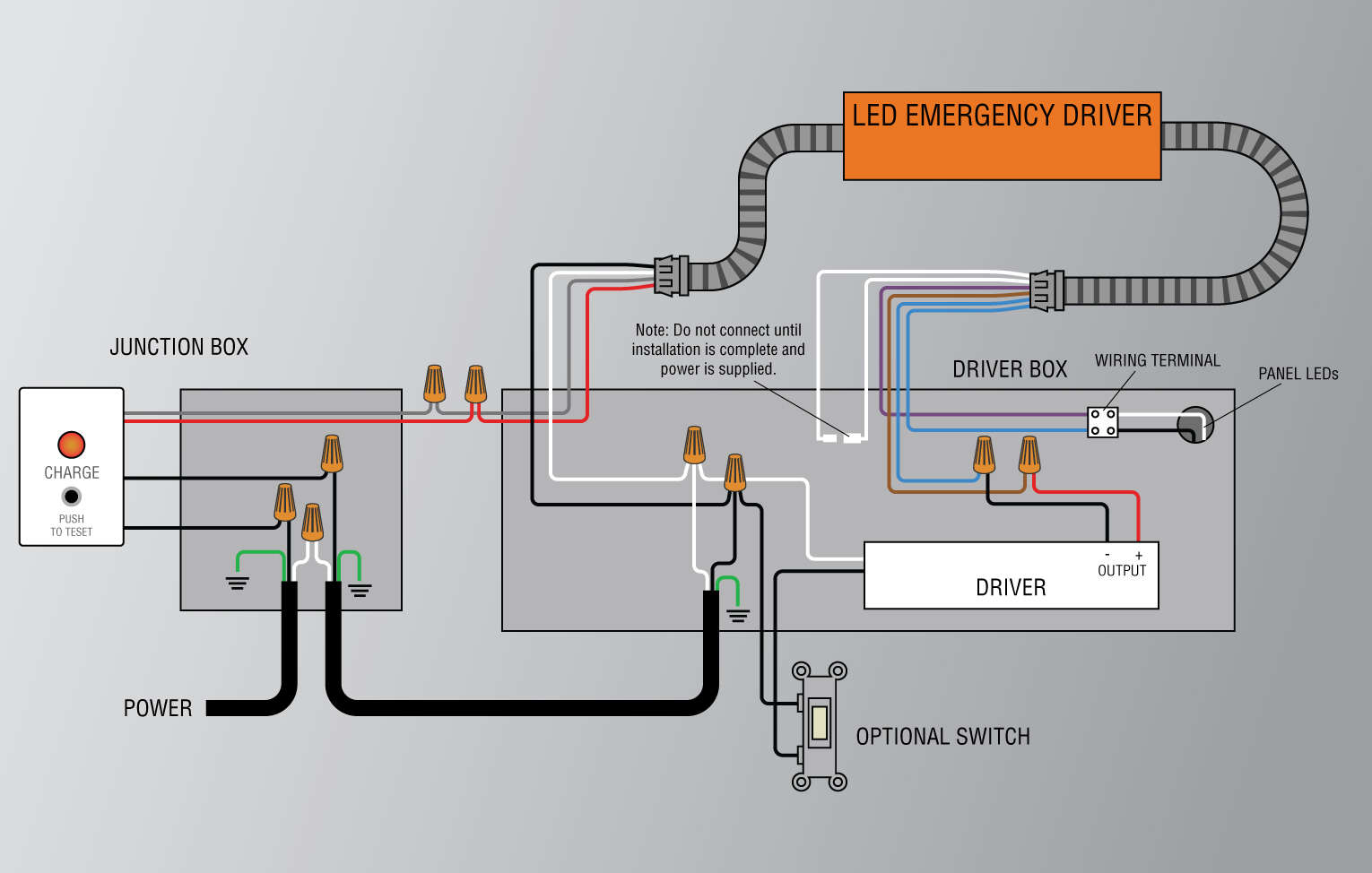
Led emergency ballast wiring diagram. I320 Emergency Ballast Reduced Profile For Linear Led Retrofit Tled And Fluorescent Luminaires. Bk 9039 Iota Ballast Wiring Diagram Free. To prevent high voltage from being present on the DEB-1W output leads red and yellow do not join the battery connector until installation is complete and AC power is supplied to the DEB-1W.
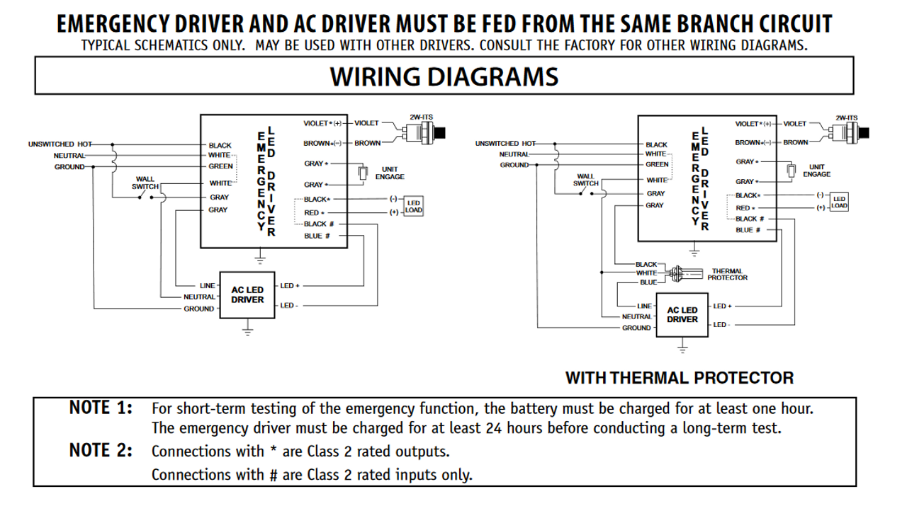
Philips Advance Ballast Wiring Diagram. WIRING DIAGRAM for EMERGENCY OPERATION at 120V-277V Emergency Ballast and AC Ballast must be fed from the same circuit Easy Installation Product Help Tech Help Line Call our experts 888 RAB-1000 2012 RAB LIGHTING Inc. Collection of fluorescent emergency ballast wiring diagram.
Disconnect AC power from the fixture. From the ballast leaving a sucient amount of wire to connect back to the 110 VAC power source. If a diagram cannot be found within this selection consult Customer Service.
Wiring diagrams for retrofit installation are supplied with each ballast. A wiring diagram is a streamlined traditional photographic representation of an electric circuit. Bodine b90 emergency ballast wiring diagram Bodine B90 Wiring Diagram Beautiful Ponent Led Diagram Symbol Wiring Wire Circuit Cr.
Remove the ballast from the tube lamp housing and save the original wiring that connected to the 110VAC. When we connect the ac supply voltage to the circuit then the starter act like short circuited and current flow through those filament located at the first and second end of the tube light and the filament generate heat and it ionized the gas mercury. May be used with other ballasts.
2 USING THE FIND COMMAND Some diagrams feature a Model List for reference. Remove lens and wiring compartment if applicable. Select the appropriate wiring diagram on back to connect the emergency ballast to the ac ballast and lamp s.
Cut all wires connected to the ballast as shown below and remove ballast as shown in Diagrams A B and C on Page 1. Wiring diagrams for option 2. Emergency Ballast Wiring Diagram wiring diagram is a simplified welcome pictorial representation of an electrical circuit.
Wiring Diagram Emergency Ballast. Select the appropriate wiring diagram to connect the emergency ballast to the AC ballast. The DEB-1W emergency ballast is approved for installation inside on top of or.
Variety of bodine b90 emergency ballast wiring diagram. This video is about the How To Connect Led Emergency Lights And Lamps Driver Tridonic Ballast Wiring Connection complete guide in UrduHindi language Is. Double-ended wiring installations of tubes require non-shunted G13 or non-shunted G13 lampholders with instructions to externally shunt.
Bodine b100 emergency ballast wiring diagram. Fulham Hotspot Led Emergency Driver Fhscp Unv 13 7wl 120 277v 7 Watt 2200 Lumen Output 90 Minute Run Time At Green Electrical Supply. When we connect the ac supply voltage to the circuit then the starter act like short circuited and current flow through those filament located at the first and second end of the tube light and the filament generate heat and it.
If you know the actual model number of the AC ballast that the emergency. Consult the factory for other wiring diagrams. Em Ballast Wiring Diagram Renault Clio Free 5pin Waystar Fr.
Ballast diagram may not necessarily take you to another Two Lamp Ballast diagram. It shows the components of the circuit as simplified forms and the power and signal links in between the devices. It shows the components of the circuit as simplified shapes and the facility and signal links between the devices.
Cut back additional wiring on opposite side of ballast as the LED Tube lamp only requires power at one end. Identify type of lampholders in fixture. Hid ballast wiring diagrams ballast wiring diagrams for hid.
To aid in locating specific diagrams each has been bookmarked and categorized in the navigation window. Manual Je Woo. Wiring Diagram Pics Detail.
Variety of bodine b90 emergency ballast wiring diagram. Fig 104 two 2 lamp instant start ballast wiring diagrams for 2-lamp emergency operation 2- 4 17- 40 w lamps only wiring diagram for 1-lamp emergency operation emergency ballast and ac ballast must be fed from the same branch circuit typical schematics only. Strip the load and neutral wires.
Bodine b90 emergency ballast wiring diagram bodine b90 emergency ballast wiring diagram Collection bodine b90 wiring diagram Best of ponent Led. Emergency ballast for led wiring diagram. Remove the ballast channel cover and install the emergency ballast either in the ballast channel see Illustrations 1 2 or on top of the fixture see Illustration 3.
EMERGENCY BALLAST RELAY HOW TO USE THE EMERGENCY BALLAST WIRING GUIDE This Document has been customized to contain a wide library of individual dia-grams for various installation applications. The diagrams are categorized primarily according to the number of lamps in the. Led Emergency Drivers And Ballasts Iota Iota Power And Lighting Systems Explanation Of Voltage And Cur Input Wiring Diagram For Ion8600 Form 9 9s 3 Wire.

Universal Everline Eld10unvl Emergency Led Driver 10 Watt 90 Minute Battery Backup For Led Fixtures 120 277v Input Voltage 15 50vdc Output Voltage Class 2 Emergency Led Driver At Green Electrical Supply

Universal Everline Eld20unvl Emergency Led Driver For Highbays 20 Watt 90 Minute Battery Backup For Led Fixtures 120 277v Input Voltage 20 50vdc Output Voltage Class 2 Emergency Led Driver At Green Electrical Supply
Philips Bodine Bsl10lst Cold Pak Compact Led Emergency Driver

How To Wire And Test An Iota Ilb Cp Emergency Driver Youtube
Emergency Ballast For Led Wiring Diagram
Led Emergency Backup Driver 25w Output 100 277 Vac Driver Input Super Bright Leds
Emergency Led Driver 15 Watts Max 25 48v Output 120 277v Input Jen Lighting Wholesale Led Lighting
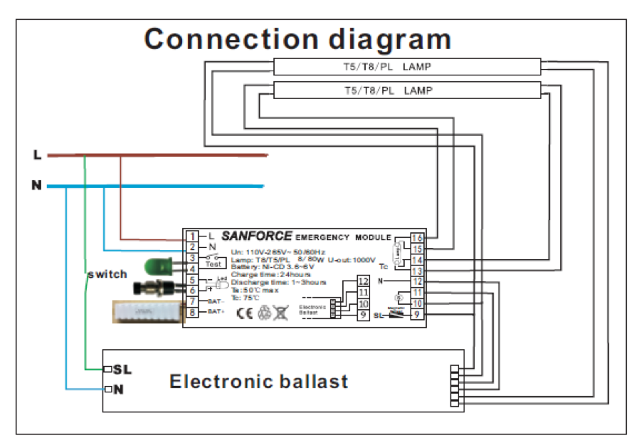
A Guide To Emergency Ballast For Led And Fluorescent Lamps Sanforce

Ufo Emergency Driver Led Ballast Ip65 170vdc
