The creators will not be held accountable for any unintentional flaws or omissions that may be found. Gas Interlock System Wiring Diagram The gas interlock system for commercial kitchens tel.
Gas Interlock System Wiring Diagram - If you're looking for video and picture information linked to the keyword you have come to pay a visit to the ideal blog. Our site provides you with suggestions for viewing the highest quality video and image content, search and find more informative video content and graphics that fit your interests. includes one of thousands of video collections from several sources, particularly Youtube, so we recommend this video for you to see. It is also possible to bring about supporting this site by sharing videos and graphics that you like on this site on your social media accounts like Facebook and Instagram or tell your closest friends share your experiences about the simplicity of access to downloads and the information that you get on this website. This site is for them to stop by this website.
Merlin Gas Ventilation Interlock System Caterkwik
Gas Valve Isolator Mains Input Wiring The mains supply must be isolated before connection.
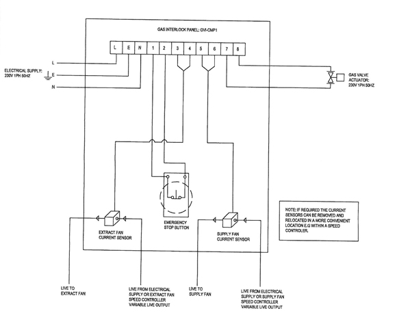
Gas interlock system wiring diagram. Ct1250 Wiring Diagram Merlin CT1250 Gas Interlock System Product Data Sheet CT1250 Wiring Diagram Mains Input 230VAC Gas Solenoid Valve Power Output 230VAC. B fan air flow pressure switch es. The writers of Gas Interlock System Wiring Diagram have made all reasonable attempts to offer latest and precise information and facts for the readers of this publication.
Mains input and gas valve terminals are clearly marked on the PCB. The Hall A Wire Chamber Gas System Ops Manual. You can read Gas Interlock System Wiring Diagram PDF direct on your mobile phones or PC.
User guide the gas interlock system for wiring diagram als3 supply gm 4 control unit failsafe practices fail safe cw 2577 interlocking merlin 2000s panel incl pressure gdp2x detection s ansul contractor talk. Wiring Diagram For Interlock Transfer Switch Portable. The GasGuard gas proving system is designed to meet the requirements of IGEMUP11 Edition 2 for educational establishments and is a BS61732009 and IGEMUP19 compliant ventilation interlock.
Fan Current Monitor Reset Button 3. The ALS3 is the straightforward way to help you to. Fan Current Monitor High Button 5.
Control unit for interlock system 14x14x6 cm. As per our directory this eBook is listed as GISWDPDF-1211 actually introduced on 4 Jan 2021 and then take about 1842 KB data size. 11-3x 11-6x endobj For a basic system to operate on a.
Maintaining the integrity of the kitchen ventilation system is critical for a safe working environment and this is detailed in British Standards BS61732009. GasGuard will ensure that the gas is isolated to prevent any. Breakaway Battery Wiring Diagram Wire Harness Diagram 5 Wire Moped Multiple Electrical Outlet Wiring Diagram Wiring Diagram Beech 300 Wiring Diagram 2008 Chevy Uplander Hall Light With Electrical Outlet Diagrams Vdo Xtreme Tachometer Wiring Diagram.
Upon receiving a fault signal from any external devices the. Please note Mains wires and low voltage wires should. Connect 230vac gas solenoid valve as detailed in wiring diagram section.
The GasGuard gas proving system is designed to meet the requirements of IGEMUP11 Edition 2 for educational establishments and is a BS61732009 and IGEMUP19 compliant ventilation interlock. Merlin CT1650 Gas Interlock System Product Data Sheet SS Northern Ltd 7 CT1650 Front PCB Wiring Diagram 1. Normally Closed Common and Normally Open.
Fan Current Monitor OnOff switches. Wiring Diagram For Gas Interlock System Diagram Wiring Diagram For Gas Interlock System. If Remote Emergency Stop Button is required this should be connected to the NC and Common terminals.
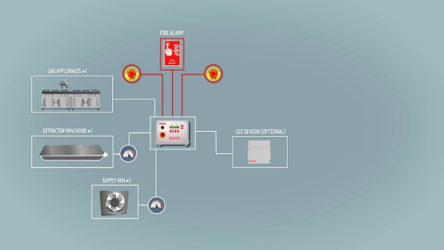
Wiring Diagram Recirculation Control Motor Replacement Rear Door Component Location Index - 13. 100 Series Gas Ventilation Interlock System INSTALLATION GUIDE 3 Installation Schematic - basic install shown in kitchen Mains rated wiring 2 core Mains rated wiring 2core earth KEY PANEL Air flow pressure switch repeat on fresh air make up fan if fitted always try to site in negative pressure To Fire Alarm panel if required. Fuel and Emissions System Circuit Diagram Except KH DTC Troubleshooting.
Rocky Jamesh Published Date. Door Interlock System At Radix. It interlocks the gas supply with the Kitchen ventilation system.
Tamper and Flow Switch Wiring Diagrams Lovely Bep2 Od Bioentry P2. Jeep Renegade 2015 2018 Service Repair Manual System. Remote EM Stop buttons and Fire Alarm input wired in series purchased separately.
Mains input 230vac 2. Read Gas Interlock System Wiring Diagram PDF on our digital library. The GasGuard is ideal for when appliances are not fitted with flame failure devices or can be used to provide additional peace of mind when they are.
GAS PROVING INTERLOCK SYSTEM Dimensions Installer Selectable Options Technical Specication Basic Operation Turning the key switch to ON will start the proving cycle by energising the Gas Valve to pressurise the system the valve will then close and the pipework is monitored for 30 seconds for pressure drops. The ALS3 is a gas interlock system for commercial kitchens. Hvac System Wiring Wiring Diagram.
User guide the gas interlock system for commercial kitchens als3 supply neatafan wiring diagram science of wedding ideas bmw m6 diagrams eternal mute furnace electronic ignition blog backgroundaccident hvac heat pump full version hd quality diagrampart lademocraziacristiana it 2008 ezgo txt pds query development er 6582 interlocking schematic User Guide The Gas Interlock System. Gas Interlock System Wiring Diagram - Electrical wiring layouts are made up of. Interfaces such as ventilation systems.
AT Interlock System Circuit Diagram Except KSKH AT Interlock System Component Location Index Except KH. User Guide The Gas Interlock System For Commercial Kitchens. BMS Selection EM Selection.
Gas Interlock System Wiring Diagram Author. It interlocks the gas supply with the Kitchen ventilation system. User guide the gas interlock system for commercial kitchens als3 supply neatafan wiring diagram automotive pictures 2020 gm 4 control unit merlin 1500s panel s northern ventilation pressure proving pack with 0 75 valve ct1250 justcatering com emergency petrochemical plants and others yokogawa electric corporation ct1200s failsafe practices fail safe design relay non ags american safety.
Wiring Diagram 184 views. If not required a link should be connected between the terminals. 28 Gas Interlock System Wiring Diagram Gas Interlock.
Fan Current Monitor Low Button 4. Signal programs preset see Wiring Diagram for details When switched on via the key switch the GasGuard Manual system provides gas to the kitchen and monitors all external.
Https Www Neatafan Co Uk Wp Content Uploads 2018 01 Als3 Operating Instructions Pdf
Merlin 1200s Gas Commercial Interlock Air Pressure Switch System 2 Solenoid Valve Catersparesuk
Https Www Neatafan Co Uk Wp Content Uploads 2018 01 Als3 Operating Instructions Pdf
Ncsp Gas Ventilation Interlock Panel Nfan Supply Stock Extractor Fans Ventilation Solutions For Homes Amp Businesses In The Uk
Gas Interlock System Wiring Diagram The Science Of Wedding Ideas
The Hall A Wire Chamber Gas System Ops Manual
Https Www Neatafan Co Uk Wp Content Uploads 2018 01 Als3 Operating Instructions Pdf
Gas Interlock Als3 Gas Supply Interlock Neatafan
Gv 2 Gas Ventilation Interlock Panel Nfan Supply Stock Extractor Fans Ventilation Solutions For Homes Amp Businesses In The Uk


