Listing price is for ONEEACH FACTORY SEALED Notes. The modular rackless design enhances cost savings and reduces replacement parts inventory.
1762 If2of2 Wiring Diagram - If you're searching for video and picture information related to the keyword you've come to visit the ideal blog. Our website gives you suggestions for viewing the maximum quality video and image content, hunt and locate more enlightening video content and images that fit your interests. includes one of tens of thousands of movie collections from various sources, especially Youtube, therefore we recommend this video that you see. This blog is for them to stop by this website.
1762 If2of2 Wiring Rockwell Automation 1762 Lxxxx Micrologix 1200 Programmable Controllers User Manual Page 61 168
MicroLogix 1500 Processor Installation Instructions 1764-IN002A-ML-P Selecting Discrete InputOutput Modules Compact Discrete InputOutput Modules Technical Data 1769-21 View power usage of expansion modules to.
1762 if2of2 wiring diagram. Rodix FEEDER CUBE VF-3CE Wiring Diagram Wiring diagram 13 pages LucidControl DI8 User Manual Operation users manual 29 pages Dynamic. Removable terminal blocks help ease the wiring task. According to the 1762 if2-of2 manual the values for a 4-20 mA range is at at 032760 while the there is a small note in the 1766 manual that says that the range of a 1762 expansion card if2-of2 for 4-20 mA is between 6240 and 31200.
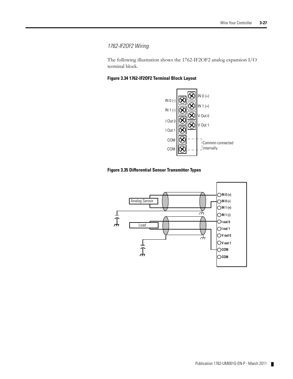
1762-IN003A-US-P Output Wiring Basic wiring1 of the 1762-OW8 is shown below. This module has Two 2 Differential inputs compatible for 0 - 10VDC and 4 - 20 mA and Two 2 single ended current and voltage signals with. Allen-Bradley 1762-IF2OF2 MicroLogix Expansion Analog Combination Module VoltageCurrent 2 Inputs2 Outputs Series B.
In the RsLogix 500 - Analog Circuits - Wiring and Programming - 0-10VDC 4-20mA lesson you learned that the Input Min. 1762-OF4 Installation Use your product. Modules can be either DIN Rail or panel mounted.
Upper and lower tongue-and-groove slots guide the module during installation and secure the module within the system. Ser A Ser B. Im also not sure about the implementation of the program that will feed the 420 mA signal to the pumps.
1 Surge Suppression Connecting surge suppressors across your external inductive load will extend the. Publication 1762-IN007B-EN-P- June 2013 Output Wiring Basic wiring of the 1762-OA8 is shown below. Will be 0 and 32767 the full voltage scale is 0-105 VDC and the full current scale is 0-21mA.
The 1762-IF2OF2 is a MicroLogix 1100 1200 1400 analog combination module. Related Manuals for Allen-Bradley 1734-OB2. Wire fragments that fall into a module.
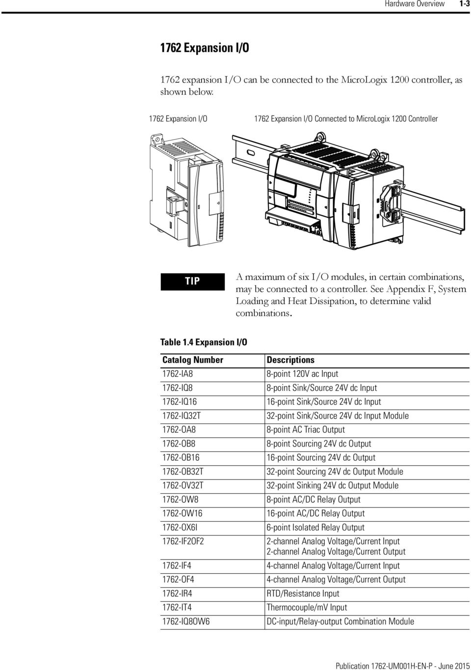
Input Module Installation Instructions 1762-IN004A-US-P Installation guide for the 1762-IF2OF2 1762-IF2OF2 Analog Input Analog IO Module Output Module Installation Instructions 1762. Our Bulletin 1762 MicroLogix Expansion IO Modules extend the capabilities of the MicroLogix 1100 1200 and 1400 controllers by maximizing flexibility of the IO count and type. Once the modules are locked together the system becomes a rugged assembly.
It shows only 0-10 volts or 4-20 mA as programmable options. No file text available Original. A write-on label is provided with the module.
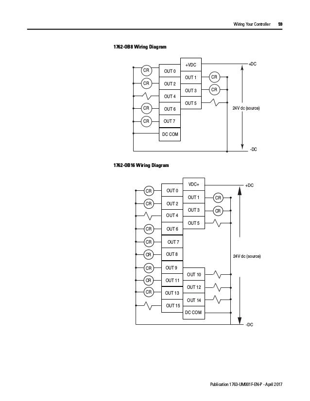
1762-OB8 1762-IF2OF2 1762-OB8 wiring manual transistor D 1762 1762-IQ8 1762 IF2OF2 Micrologix 1200 1762-OA8 1762 OB8 Text. IO wiring can be routed from beneath the module to the IO terminals. Consider the following when wiring your system.
Analog Wiring 1762 If2of2 Input Type Selection Rockwell Kinetix 3 Component Servo Drive Ppt Video Online Download 1766 L32bxb Allen Bradley 1766 Plc I O Module 20 Inputs 12. Allen-Bradley 160-NX3 User Manual. 1762-IN005A-US-P MicroLogix Analog InputOutput Module Installatio n Instructions Author.
MicroLogix 1762-IF2OF2 Analog InputOutput Module 13. Support seamless bridging with data control and collection over the same network. Terminals are electrically isolated from the system.
A write-on label is provided with the module. Wiring Diagrams 1764-IN001A-ML-P A description on how to install the processor into the MicroLogix 1500 Base unit. Mark the identification of each terminal with permanent ink and slide the label back into the door ATTENTION Be careful when stripping wires.
From the information in step 2 enter the following into the SCP instruction. Here is Page 22 from the 1762-IF2OF2 Analog InputOutput Module Installation Manual dated April 2011 Configuration Data File beginning on Page 21. Support SIL 3 PLe integrity L4xS controllers only Permit on-line editing forcing and other standard activities while securely isolating safety functionality L4xS controllers only Integrate with 1769 Compact IO modules.
Product Drawings Wiring Diagrams Release Notes. Allen-Bradley MicroLogix 1762-IF2OF2. Mark the identification of each terminal with permanent ink and slide the label back into the door.
Publication 1762-IN005C-EN-P - July 2013. MicroLogix 1200 Programmable Controllers and Expansion IO User Manual 1762. Items are shipped the next business day once payment is received and cleared.
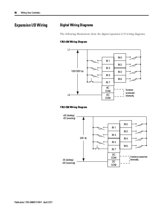
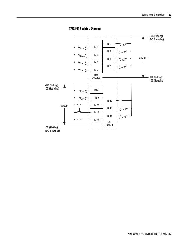
Channels are not isolated. MicroLogix 1762-IF2OF2 Analog InputOutput Module 3 Publication 1762-IN005C-EN-P - July 2013 Environment and Enclosure Preventing Electrostatic Discharge ATTENTION This equipment is intended for use in a Pollution Degree 2 industrial environment in. 1762-IQ8wiringdiagram datasheet cross reference circuit and application notes in pdf format.
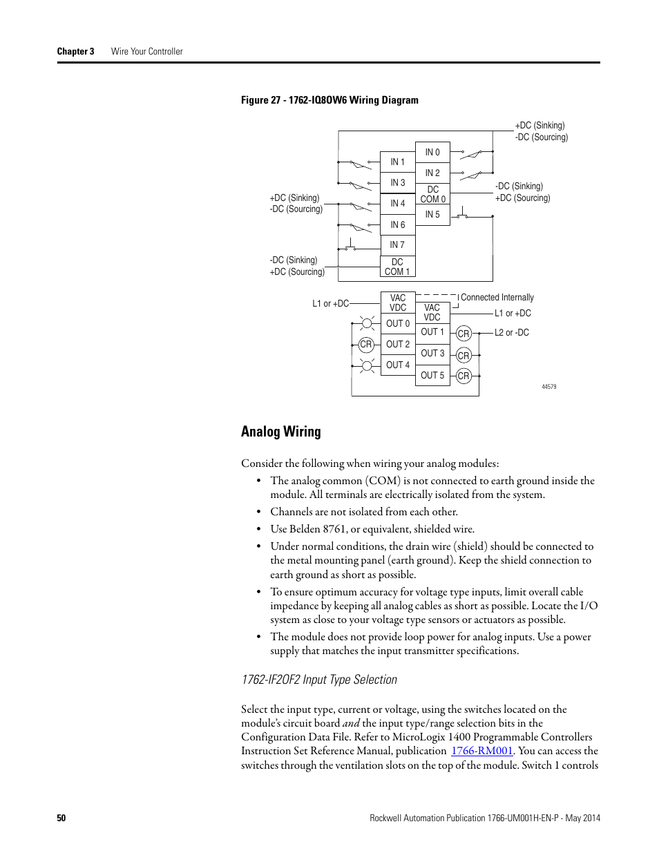
0 set dip switches on 1762-IF2OF2 1 create new RSLogix project 2 configure Processor 3 read IO config 4 perform ADV Config for the 1762-IF2OF2 changing from 10v to 4-20ma 5 save configuration 6 download to 1200 7 exit RSLogix 8 cycle power to 1200 9 bring RSLogix back up and go Online 10 examine IO values either in the data files or thru CDM. The analog common COM is not connected to earth ground inside the module. 1762-OB8 1762-IF2OF2 1762-OB8 wiring manual transistor D 1762 1762-IQ8 1762 IF2OF2 Micrologix 1200 1762-OA8 1762 OB8 Text.

Rockwell Automation 1763 Micrologix 1100 Programmable Controllers User Manual User Manual Page 67 256

Wiring Analog Input Module Plcs Net Interactive Q A
Manual De Plc Micrologix 1100
Manual De Plc Micrologix 1100
Manual De Plc Micrologix 1100

Sale 27 95 Phd Input Set Point Module 9800 01 0400 In 2021 Phd Point Personalized Items

Lab Plc Allen Bradley Ab 3 F 17 2555
Micrologix 1200 Programmable Controllers Pdf Free Download
Analog Wiring 1762 If2of2 Input Type Selection Rockwell Automation 1766 Lxxxx Micrologix 1400 Programmable Controllers User Manual User Manual Page 64 406
