8 vr2 technical manual sk77898 8 curtiss wright pg drives technology about this manual the technical manual gives an introduction to the vr2 control system. Some will only occasionally be.
Vr2 Controller Wiring Diagram - If you're searching for picture and video information linked to the keyword you have come to visit the ideal blog. Our site provides you with suggestions for seeing the highest quality video and picture content, hunt and find more informative video articles and graphics that fit your interests. comprises one of thousands of video collections from several sources, particularly Youtube, so we recommend this video that you see. This site is for them to visit this site.

Quickie Rhapsody Service Manual Pdf Free Download
The s drive family the s drive scooter controller family is the most advanced.
Vr2 controller wiring diagram. Vr2 c ontrol ystem drives technology drive motors the control system is designed to be connected to permanent magnet dc motors fitted with suitable gearboxes and solenoid. Benson VR2 Range OandM Apr2013 Issue12. You may also like.
Proven connectivity with Allen-Bradley Modicon AEG Schneider General Electric Johnson Yokogawa Honeywell Fisher-ProVox Bailey and other PLCDC devices eliminate the risks associated with digital integration of weight information into the process control environment. Check all the connections and leads between the motor and the battery. Control in noisy process environments.
By Burgerman Tue Jul 08 2014 956 pm. Check the battery connections. 17mm Deep Socket wrench 13mm combination wrench Cutter for zip-tie Needle nose pliers.
An indication that the control system has gone to sleep. In the case of the VR2 the control system will turn off completely. Wiring Diagram 33-67-161 VRA 12-60 VRC 12-30 Auto ignition OnOff.
17mm Deep Socket wrench 13mm combination wrench Cutter for zip-tie Needle. If you do you may shorten the. 113 The LCp-200 Front Panel.
Basic Tool List Main Wiring Diagram Wiring Diagram for VR2 Controller Package Basic Tool List The following list of tools should enable any task to be dealt with. If you want to adjust this time or remove the function altogether go to the Operation group. Provide disconnect and overload protection as required.
Check the battery connections. The s drive minimising the wiring variants and allows. View and download pg drives technology vr2 series operation and installation manual online.
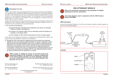
VR2 Technical Manual SK77898-8 Curtiss-Wright PG Drives Technology ABOUT THIS MANUAL The Technical Manual gives an introduction to the VR2 Control System. Do not use the onoff button to stop the wheelchair unless there is an emergency. 8 vr2 technical manual sk77898 8 curtiss wright pg drives technology about this manual the technical manual gives an introduction to the vr2 control system.
If using electrical conduit the attachment to the actuator must be made with fl exible conduit. To awake the system switch off and on again. Wiring Diagram 33-68-007 VRC 42 Auto ignition OnOff WARNING NEUTRAL RESET SEQUENCE CONTROLLER.
Pg drives technology s drive d50770 scooter controller with wiring harness 0 results. 8 vr2 technical manual sk77898 8 curtiss wright pg drives technology about this manual the technical manual gives an introduction to the vr2 control system. 8 vr2 technical manual sk77898 8 curtiss wright pg drives technology about this manual the technical manual gives an introduction to the vr2 control system.
8 vr2 technical manual sk77898 8 curtiss wright pg drives technology about this manual the technical manual gives an introduction to the vr2 control system. The icons used are. The s drive combines the proven reliability of pg drives technology design with all of the safety features expected from such a respected mobility electronics manufacturer.
When a control system has detected a trip a system trip is indicated. Controller s drive 120a pg 6. Always read the controller manufacturers installation.
Wiring Diagram 33-67-630 VRC 42-50 Auto ignition OnOff. Need service manual or electrical wiring diagram. VR2 Controller Schematic Diagram.
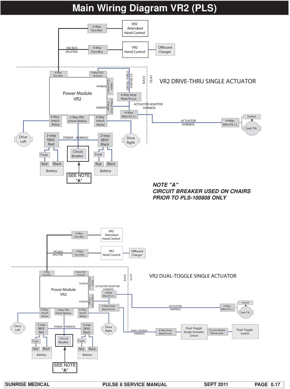
Main Wiring Diagram VR2 PLS 017 Main Wiring Diagrams Rnet PLS 018 Main Wiring Diagram VR2 and RNET PLS6APLS6B 019 Main Wiring Diagrams Actuators PLS6APLS6B 020 VR2 Dual Attendant System Connection Basic Tool List 021 Battery Connection Test 11 Check Battery Wire Harness 12 Circuit Breaker Test 12 Main Harness 12 Section 2 VR2 Remote Controller Display 21. This is because the control system is able to detect problems in other electrical components motors batteries solenoid brakes etc or more importantly the wiring to them. I would fit one of these with a dab of epoxy to whatever gets hot.
Some will only occasionally be needed but it is advisable to own or have access to them. The control system goes to sleep after a programmed period of time. Freewheel switch trip the freewheel switch is activated or the manual brake disengagement mechanism is operated.
VR2 Controller Operation 1 Operating Your Powerbase Wheelchair ONOFF BUTTON AND BATTERY GAUGE The onoff button applies power to the control system electronics which in turn supply power to the wheelchairs motors. At 40C it starts the fan. 8 vr2 technical manual sk77898 8 curtiss wright pg drives technology about this manual the technical manual gives an introduction to the vr2 control system.
Pg drives technology s drive wiring diagram. Wiring Diagram 33-68-001 VRA 12-60 VRC 12-30 Auto ignition OnOff WARNING NEUTRAL RESET SEQUENCE CONTROLLER. Some will only occasionally be needed but it is advisable to own or have access to them.
Wiring Diagram 33-68-010 VRC 50-60 Auto ignition OnOff. Basic Tool List Main Wiring Diagram LEFT MOTOR 24vBRAKE SOLENOID RIGHT MOTOR 24vBRAKE SOLENOID CHARGER AC INPUT -LEFTBATTERY CIRCUIT BREAKER -LEFTBATTERY --FUSE FUSE FUSE Wiring Diagram for VR2 Controller Package Basic Tool List The following list of tools should enable any task to be dealt with. Check the battery connections.
Wiring Diagrams - VR² Unit Heaters. 8 vr2 technical manual sk77898 8 curtiss wright pg drives technology about this manual the technical manual gives an introduction to the vr2 control system. This is because the control system is able to detect problems in other electrical components motors batteries solenoid brakes etc or more importantly the wiring to them.
Use copper twisted pair conductors only. Pg drives technology s drive d50770 scooter controller with wiring harness 0 results. With wiring diagrams and follow all applicable local and national codes.
Basic Tool List Main Wiring Diagram Wiring Diagram for VR2 Controller Package Basic Tool List The following list of tools should enable any task to be dealt with.
Quickie Pulse 6 Service Manual Pdf Free Download

Vr2 Control System Pg Drives Technology Manualzz
Vr2 Attendant Control Basic Operating Instructions Manualzz

Quickie S636 W Rnet Vr2 Replacement Parts By Quickie Quickie Wheelchairs Com

Quickie Pulse 6 Service Manual Pdf Free Download
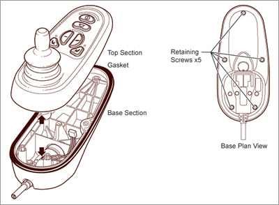
Vr2 Disassembly Of The Jsm Curtiss Wright Service Center
Http Www Meritsusa Com Page Files Manuals Owner S 20manual 20for 20vr2 20controller 20 Pn75271088 Pdf

2009 Quickie Rhythm Service Manual Supplement Pdf Free Download

Jazzy Select 6 Replacement Parts By Pride Mobility Southwestmedical Com
