This is a simple active antenna booster. To the antenna and both TV sets are receiving signals from the antenna.
Rv Tv Antenna Booster Wiring Diagram - If you're looking for picture and video information linked to the key word you have come to pay a visit to the right site. Our site provides you with hints for viewing the maximum quality video and image content, search and find more enlightening video articles and images that match your interests. comprises one of thousands of video collections from several sources, especially Youtube, so we recommend this movie for you to see. You can also contribute to supporting this website by sharing videos and graphics that you enjoy on this site on your social media accounts like Facebook and Instagram or tell your closest friends share your experiences about the simplicity of access to downloads and the information you get on this site. This site is for them to stop by this website.

Pin On Sara
Make sure the antenna is in the operating position up and pointed at the station desired.

Rv tv antenna booster wiring diagram. TV Antenna wiring diagram. Keystone rv cable tv wiring diagram. Is it 100 correct NO.
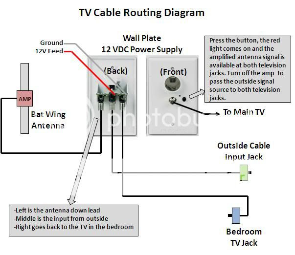
If your booster LED is flickering when you turn it on I can only guess you have a 12V feed problem. Figure 4 Antenna Set 2 Cable INSTRUCTIONS RV WALL PLATE POWER SUPPLY MODELS RV-7012 RV-7032 RV-7042 Made in USA. A short coax cable is ran from the TV antenna output to the preamplifier input.
Figure 3 below identifies each line. I can only guess all units are configured this way. Otherwise the arrangement will not function as it should be.
With resolution 2151px x 1633px. Rv tv antenna booster wiring diagram. Posted by Denny Duplessis on 26th Jan 2019.
Use a good lap sealant recommended by your RV manufacturer for rubber or fiberglass. Keystone rv wiring diagram sample keystone rv wiring diagram elegant. Rv tv antenna booster wiring diagram.
Awesome Winegard Antenna Booster Wiring Diagram Page 2 Satellite TV System RA 7296 User Guide owners manual installation instructions winegard rv antenna owners manual installation instructions winegard rv antenna slide all parts over elevating shaft and install. For instance if a module will be powered up and it sends out a signal of fifty percent the voltage in addition to the technician would not know this he would think he provides a problem as this individual would expect a new 12V signal. Here is a picture gallery about winegard rv antenna parts diagram complete with the description of the image please find the image you need.
Rv Antenna Diagram Rv Antenna Wiring Diagram Wiring Diagram pertaining to Winegard Rv Antenna Parts Diagram image size 479 X 312 px and to view image details please click the image. Rv Antenna Diagram Rv Antenna Wiring Diagram Wiring Diagram pertaining to Winegard Rv Antenna Parts Diagram image size X px and to view image details please click the image. Our 25 foot cable works well for the EZ HD antenna.
The circuit operates in the UHF band and has a gain of 15dB. Turn the tv antenna power booster located inside the unit to the off position in some units turn the booster to the cable position. Turn the tv antenna power booster located inside the unit to the off position in some units turn the booster to the cable position.
Neon lamp inverter circuit. 36 db high performance vhf uhf fm hdtv signal amplifier great for cable tv. FOR YOUR WINEGARD RVTV ANTENNA RAISING ANTENNA TO OPERATING POSITION Turn elevating crank clockwise in UP direction about 13 turns or until some resistance to turning is noted.
How to Hook Up TV to RV Antenna with 3 Steps. Turn the tv antenna power booster located inside the unit to the off position in some units turn the booster to the cable position. Neither outlet will work unless power supply switch is ON.
The goal is to route the cable from the outside of the RV to the faceplate so we can attach a satellite dish. They look similar to figure 1 below and usually include a 12 volt outlet. The Red wire is 12 volt the white wire is the neutralground.
Keystone rv wiring diagram elegant. The input signal is. For the last couple of decades the batwing antenna has been the primary antenna that has been put on the recreation vehiclesBy cranking it up and turning on the booster it allows you to bring in the even distant television signal.
Note that the 12 volt line red is live. Videos you watch may be added to the TVs watch history and influence TV. Tv antenna booster circuit diagram.
Capacitors C2C3 C4 C5 and inductors L3 L4 forms a UHF band pass filter. It is best to find the fuse for. How to install a tv antenna.
TV wiring 2016 Durango 315RKDpdf 37191 KB What is not mentioned is the amount of signal loss through the splitters. The circuit shown here is of a TV antenna booster based on the transistor BF180. Here is a picture gallery about winegard rv antenna parts diagram complete with the description of the image please find the image you need.
Each part should be set and linked to different parts in particular manner. Winegard Rv Antenna Parts Diagram entitled as Rv Tv Antenna Booster Wiring Diagram Wire Center Winegard Rv Antenna Parts Diagram - also describes Rv Tv Antenna Booster Wiring Diagram WIRE Center and labeled as. Connect a new coax to the antenna outside on the roof like above however run the coax to the closest side of the rig and drill a hole to run the coax inside to a side cabinet.
AMPLIFIED MODELS ONLY Turn power supply ON to use either front or rear TV outlet. How to use a RV antenna Booster - YouTube. If playback doesnt begin shortly try restarting your device.
However putting the park cable into the satellite input provides tv. The 4 foot cable is best for the HD Stacker antenna. Here is a generic diagram of the satelliteantenna wiring.
Rv Tv Antenna Booster Wiring Diagram To properly read a electrical wiring diagram one has to know how the components in the system operate. INSTRUCTIONS RV WALL PLATE POWER SUPPLY. Turn the tv antenna power booster located inside the unit to the off position in some units turn the booster to the cable position.
Heres a simple schematic of a tv transmitter circuit or video transmitter circuit which is. The cable works fine with the TVs but it does not with the satellite input.

Electrical Wiring Digital Tv Wiring Diagram 94 Diagrams Electrical Car Antenna Digital Tv Wiring Dia Electrical Wiring Diagram Electrical Wiring House Wiring

Inverter Wiring Diagram For House Wiring Diagram Database Alt Image
33 Tv Antenna Schematic Diagram

Gy8 8cc Engine Diagram Harga Wiring Diagram Home Wiring Diagram Diagram

Electrical Wiring Sky Compatible Distribution Amplifier Digital Tv Wiring Diag Digital Tv Wiring Diagram 94 Wiring Diagram Satellite Receivers Satellites
Tv Antenna Booster Campground Cable Jayco Rv Owners Forum

3 Wire Alternator Wiring Diagram In 2021 Alternator Alternator Wiring Diagram Wiring Diagram
Home Audio Wiring Diagram In 2021 Pioneer Car Stereo Wiring Diagram Car Stereo
33 Tv Antenna Schematic Diagram
