If you went with the RIB relay you would only need to get a low voltage line over to the. To use Remote Test Input the WhiteBlack wire must be de-energized.
Rib Relay Wiring Diagram - If you're searching for video and picture information linked to the keyword you've come to visit the right blog. Our site provides you with hints for seeing the maximum quality video and picture content, search and find more informative video content and graphics that fit your interests. comprises one of tens of thousands of video collections from several sources, especially Youtube, therefore we recommend this video for you to see. This site is for them to visit this site.

Diagram 12v Relay Wire Diagram Full Version Hd Quality Wire Diagram Avdiagrams Fanofellini It
How about a RIB relay AutoCAD drawing.
Rib relay wiring diagram. This will eliminate external variables and leave only the relay as shown in Figure 1. A wiring diagram is a simplified standard pictorial depiction of an electrical circuit. A wiring diagram is a straightforward visual depiction of the physical links as well as physical format of an electrical system or circuit.
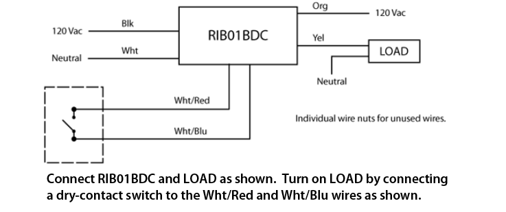
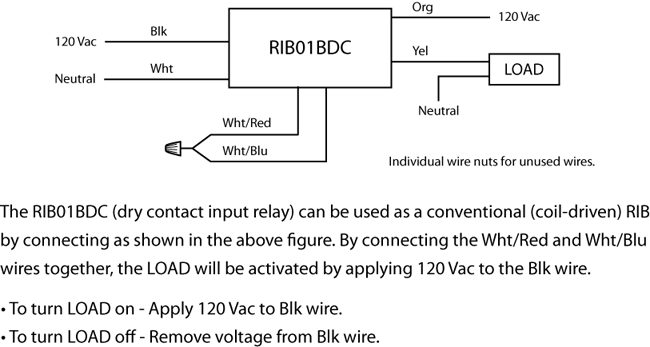
Close WhiteRed wire to WhiteBlue wire to activate relay. The WhiteBlack wire must be on the same branch circuit as the Black wire. A wiring diagram is a simplified standard pictorial depiction of an electrical circuit.
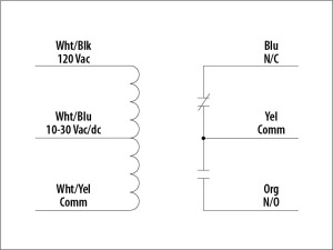
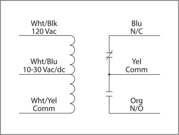
Set the multimeter to read resistance and connect the probes to the Blue and Yellow wires which is the Normally Closed NC contact. The relays come mounted and pre-wired in a housing saving the installer the time trouble and expense of buying separate components relay socket mounting rail and enclosure and assembling them on the job or at the shopRibu1c Wiring Diagram - Worksheet And Wiring Diagram wiring diagram Rib Relays. Rib Relayswiring diagram Rib Relays.
Then you should know about a terrific resource on the Functional Devices website. Verify normal contact states. November 20 2019 1 Margaret Byrd.
From the Functional Devices website you can download RIB Relays Data Sheets Wiring Diagrams AutoCAD Drawings and Visio Drawings all in one place. May 12 2019 by Larry A. Rib Relay Schematic.
Class 2 Remote Test Input NO for button controller or re alarm panel Remote Test Button Model ESRTB sold separately H N -0-10V Dimmer Control. Or a RIB relay Visio drawing. Troubleshooting rib relays faq functional devices inc using to control bathroom wiring up a relay heating help lrl24sb enclosed products in fountain pump as 3 or.
From the Functional Devices website you can download RIB Relays Data Sheets Wiring Diagrams AutoCAD Drawings and Visio Drawings all in one place. Functional Devices is the established leader in the HVAC Building Controls and Energy Management industries for American designed and manufactured building automation and control devicesH1c Rib Relay Wire Diagram. The Relay In A Box RIB Power Series controls most BAS HVAC low-horsepower motor and lighting applications.
Posts about RIBU1C written by RibRelaysFAQ. Collection of rib relay in a box wiring diagram. Rib Relay Wiring Diagram.
How about a RIB relay AutoCAD drawing. Rib Relay Wiring Diagram For Baseboard Heaters. Ribu1c wiring diagram Typical Relay Wiring Diagram New Ribu1c Relay Wiring Diagram Valid Wiring Relay Diagram Wiring.
Wiring Diagram and Schematic Role. Functional Devices is the established leader in the HVAC Building. On Rib Relay Wiring Diagram For Baseboard Heaters.
It reveals the components of the circuit as simplified shapes and the power as well as signal connections in between the tools. Rib Relay Dpdt Wiring Diagram Wiring Diagram Rib Relay Wiring Diagram Wiring Diagram includes several in depth illustrations that show the relationship of varied products. RIB21CDC Enclosed Relay 10 Amp SPDT Class 2 Dry Contact Input 120-277 Vac Power Input RIB21CDC-RD Red housing RIB21CDC-N4 NEMA 4X housing UL508 only SPECIFICATIONS DRY CONTACT INPUT RELAY.
From the Functional Devices website you can download RIB Relays Data Sheets Wiring Diagrams AutoCAD Drawings and Visio Drawings all in one place. Need a RIB relay wiring diagram. It reveals the components of the circuit as simplified shapes and the power and also signal links in.
Directly startstop load and current sensing all in one package no external ring is needed Wire colors to Load and 60 Hz ac differ depending on the model being used. Need a RIB relay wiring diagram. Collection of rib relay wiring diagram.
Then you should know about a terrific resource on the Functional Devices website. It consists of guidelines and diagrams for various kinds of wiring techniques. It reveals the components of the circuit as simplified shapes and the power as well as signal connections in between the tools.
Wiring Up A Rib Relay Heating Help The Wall Troubleshooting Rib Relays Functional. Rib Relay Wiring Diagram What is a Wiring Diagram. The relays come mounted and pre-wired in a housing saving the installer the time trouble and expense of.
Rib Relay In A Box Wiring Diagram welcome to our site this is images about rib relay in a box wiring diagram posted by Maria Rodriquez in Diagram category on Nov 12 You can also find other images like wiring diagram parts diagram replacement parts electrical diagram repair manuals engine diagram engine scheme wiring harness fuse box vacuum diagram timing belt timing chain brakes Looking for a Relay Wiring Diagram. Variety of ribu1c wiring diagram. Click on the image to enlarge and then save it.
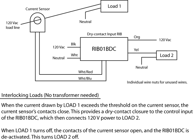
If more than one dry contact RIB shares a single dry contact input WhiteBlue must be common. Relay and Current Sensor in One. This could limit you to installing it near the panel box.
H1c rib relay wire diagramFAQ. Remove all wire connections to the RIB. The Functional Devices Relay In a Box RIB Power Series controls most BAS HVAC low-horsepower motor and lighting applications.
Ribu1c wiring diagram Wiring Diagram for Standard Relay Best Ribu1c Wiring Diagram. Configurations are either YELLOW ORANGE BLUE YELLOW or ORANGE ORANGE. A wiring diagram is a streamlined standard photographic representation of an electric circuit.
Collection of rib relay in a box wiring diagram. Or a RIB relay Visio drawing. Input can also be sent by a controller.

Faq Functional Devices Inc

Wiring Diagram For Dry Contact Relay
Wiring Diagram Rib Relays
Troubleshooting Rib Relays Functional Devices Inc
Troubleshooting Rib Relays Functional Devices Inc
Faq Functional Devices Inc
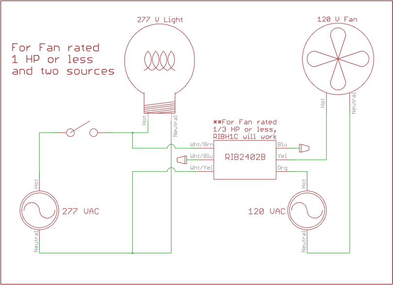
Using Rib Relays To Control Bathroom Fans Lights Functional Devices Inc
Faq Functional Devices Inc
Faq Functional Devices Inc
