I have cleaned the plastic wiring mat behind the cluster. Use with common refrigerants as well as air water and other non-corrosive fluids.
Penn Oil Pressure Switch Wiring Diagram - If you're searching for picture and video information related to the keyword you've come to pay a visit to the ideal site. Our website gives you hints for viewing the maximum quality video and picture content, hunt and find more enlightening video articles and images that match your interests. comprises one of tens of thousands of movie collections from several sources, especially Youtube, therefore we recommend this video for you to view. You can also contribute to supporting this site by sharing videos and images that you enjoy on this site on your social media accounts like Facebook and Instagram or educate your closest friends share your experiences about the ease of access to downloads and the information that you get on this site. This blog is for them to visit this site.

Air Fuel Ratio Gauge Wiring Diagram Gooddy Org In Aem Throughout Electrical Diagram Diagram Gauges
10-12 123-1067 terminal 14 full ins.

Penn oil pressure switch wiring diagram. Pressure switch wiring diagram. The P400 switch continuously monitors net lube oil pressure and the P545 control locks out the compressor if lube oil pressure falls below the manufacturers recommended net pressure for longer than the recommended lube oil time delay. 10-12 123-1066 terminal 14 full ins.
P545 Series electronic lube oil controls are used for refrigeration compressors whose oil pump accepts a single-point differential pressure switch. If oil pressure drops too low this time the differential switch will typically open signaling the PCB to begin the timing that was handled by the. This is net oil pressure to the bearings.
Power on the line voltage terminal and L supply the PCB printed circuit board with power while M and L act as the control circuit. Does anyone have knowledge of this. The purpose is the same.
The OSP1 Copleland oil pressure switch has a normally closed relay contact which opens if the oil pressure falls too low for too long. Subtract the crankcase pressure from the oil pressure gage reading. Dual voltage switch wiring diagram green jumper line out view back of140-1109 dual voltage switch showing wire conection from motor for 1hp 15hp and 2hp only 123-1067 terminal 14 full ins.
Obtain the compressor manufacturers net oil bearing pressure specifications as soon as. 2 Switch differential is approximately 5 psi 34 kPa. The oil pressure sending unit is new as well as the oil pump and engine.
P77 Series pressure controls are precision-engineered for fan cycling pressure applications. Flare nut Style 13 is standard. Wiring Diagram OPSwith Auxillary Relay KD Alarm Integration.
WHA-P400-xxx is the two-wire harness supplied with the P545 control and the P400 switch. The PCB monitors the differential pressure switch which is typically a brass assembly threaded directly into the oil pump. Ambient compensation gives uniform time delay regardless of temperature.
Literally a circuit is the path that permits power to flow. Electromechanical and electronic options are available to fit your specific application. Pressure switch wiring diagram A Novice s Guide to Circuit Diagrams.
When I rev the engine I can see the gauge move slightly. Ensure equipment operates safely and cost-effectively with controls that maintain proper operating temperature and help prevent over-cooling or overheating. 3 Replaces Ranco P30-5826 4 Replaces Ranco P30-5827 5 Replaces Ranco P30-5827 Includes alarm wire 6 Replaces Carlyle CarriereCode No.
Customize to your application with automatic and manual reset and. The control scale setting should be 9 psi 62 kPa. The oil pressure differential switch breaks the control circuit and shuts down the compressor.
The single-pole double-throw switch lets you install alarms or other control circuits. MP and MP oil differential pressure switches. Proven reliable pressure sensing elements -- several million in use.
The wire routed to the left hand side of the engine the oil pressure switch will be installed in place of the banjo bolt indicated. If the net oil pressure. WHA-P400-xxx WHA-P400-xxx Test Switch Does not function 2 2.
The first diagram shows the function of the. Net oil pressure oil pump pressure minus crankcase pressure required to the bearings is 9 psi 62 kPa. In mounting and wiring with most PowerPenn P28 controls.
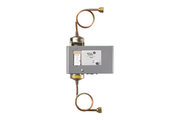
1 -- Exterior of Series P45. When the P445 Control is wired to a P400 Switch the Test button may operate when first powered. Obtaining from factor A to aim B.
To clarifyif you keep the relay then you can leave the jumper and wire 230v to the 230 term and to the one side of the relay coil the other side to M on the ofc. This method will work for any pump that runs directly off of a pressure. Time delay relay incorporates trip-free manual Fig.
The switch differential is 5 psi 34 kPa. L and M with jumper removed is just a switch. Oil pressure failure switch.
An initial appearance at a circuit layout may be complex yet if you can check out a subway map you can review schematics. Refer to the P32 Series Sensitive Differential Pressure Switch Product Bulletin LIT-125435 for important product application information. P32 S er ies Action on Incre ase of Pressure Y R B P28 Action Diagram p32eps Features.
P45 Series Typical Wiring Diagrams Illustrating Use of Oil Pressure Cutout Controls Technical Bulletin Created Date. Remove the banjo bolt from the left side of the bike and replace it with the oil pressure switch you may need to loosen the engine mounting bolts. 12-16 typ4 places 140-1109 dual voltage switch.
With P400 Switch P545 Control and P400 Switch Wiring Harness 1 1. Crimp solder a ring terminal to the end of the wire. This switch does not have a fault signal terminal.
In this video we show you the best way to a pressure switch for 115V and 230V pumps. Time delay relay energizes at 9 psi 61 kPa pressure difference de-energizes at 14 ps 97 kPa ifference. P32 Series Sensitive Pressure Switch Description This differential pressure switch is used to sense pressureair flow in ducts.
The jumper is removed if using different voltages and a 4 wire hook-up. I believe that there is a version of this switch which has a fault signalling terminal. Refrigeration oil pressure switch wiring diagram - Industrial.
Set the cutout pointer 6 to 8 PSI 41 to 55 kPa below the established running net oil pressure. All of the other gauges work fine but the oil pressure. When I start the jeep the pressure goes from 0 to 80.
Upon initial start of the compressor the time delay relay energizes.
Lube Oil Controls

Engine Indicator Diagram Yamaha

Pin On Electrical Diagram

Wiring Diagram Electric Oil Pressure Gauge Inspirationa Ecotec Electrical Diagram Oil Pressure Diagram

Ae1275
Oil Safety Controllers And Their Circuits

Ae1275

Ae1275

Wiring Mp Differential Pressure Switches Youtube
