Best of miller 14 pin connector wiring diagram allowed to be able to my website on this period im going to explain to you regarding miller 14 pin connector wiring diagramand today this can be the very first graphic. C810 1425 Tig Foot Control Pedal For Miller Rfcs 14 043554 14 Miller Xr M Wire Feeders And Guns Technical Manual Kf801189 Welder Wiring Diagram Eyelash Me Millermatic 141 Mig Welder 907612 Miller Gas Welder Diagram Wiring Schematic Diagram Owners Miller Welding Manualzz 8ea Lincoln Sa 200 Welder Wiring Diagram Wiring Resources.
Miller Rfcs 14 Wiring Diagram - If you're looking for video and picture information related to the keyword you've come to pay a visit to the right blog. Our site provides you with suggestions for seeing the highest quality video and picture content, hunt and locate more enlightening video content and graphics that match your interests. comprises one of thousands of video collections from various sources, particularly Youtube, so we recommend this movie for you to see. You can also bring about supporting this site by sharing videos and graphics that you enjoy on this blog on your social media accounts such as Facebook and Instagram or educate your closest friends share your experiences concerning the ease of access to downloads and the information that you get on this site. This blog is for them to visit this site.

Tig Foot Control Cross Reference Guide Ssc Controls Tig Pedals
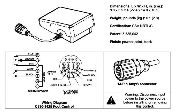
Heres a wiring diagram for a 14 pin rfcs 14 and 6 pin rfcs 6l foot control.

Miller rfcs 14 wiring diagram. The RFC-14 was the original 14 pin control built in the same metal box as the RFC-23A and using the same size resistor with the sliding brush. If you look at the face of the connector next to the pins you should see the pin markings A B C. This unit and these.
Diagram m 14 full version hd quality diagramical fimaanapoli it rfc 23a remote foot control miller 6 pin plug information 7 connecting welding and weld cable electric 22a user manual page 15 32 rhc 3gd25b owner s manualzz 4 shielding gas 5 setting optional wire sd meter range switch 22p12 16 28 the ssc controls company kd000000 weldingweb. Disconnect foot control from welding power sourcegen-erator before changing loca-tion of cord. Normally of the machine has a pilot light that lights when the machine is ON.
The manual for your power source will have a wiring diagram for your 14 pin plug to service a feeder. Remove screw that holds cord in its factory installed location. With a meter on AC Voltage check between pins A B.
HOW TO IDENTIFY THE 14 PIN CONNECTOR ON YOUR MACHINE. Changing Cord Location On RFCS-5HD And RFCS-14HD Models. Miller 14 Pin Connector Wiring Diagram wiring diagram is a simplified normal pictorial representation of an electrical circuit.
With the machine turned on the cooling fan may or may not run with the machine on. The newer lower plastic RFCS-14 uses a small 2 watt potentiometer. For miller and hobart machines with 14 pin plugs and 1k potentiometers.
New design increases stability with a larger base and a heavy 20 ft cord that can exit the front back or either side of the pedal. Both do the same job. Miller RFCS-14 HD Foot Control 194744 The Miller RFCS-14 HD heavy-duty foot control is compatible with all Miller solid-state power sources equipped with a 14-pin receptacle AFTER serial JK674521.
So ideas if you want to get all of these great images regarding miller 14 pin connector wiring diagram click save link to store the pictures in your personal computer. MILLER STYLE 14 PIN RECEPTACLE DIAGRAM. It shows the components of the circuit as simplified shapes and the capability and signal associates along with the devices.
For Miller Welders Wiring Diagram and Test Instructions How to check the potentiometer. Krpa 11dg 24 wiring diagram. Miller 14 pin connector wiring diagram.
The wire colors and connections are the same but the pin locations are different. Replacement parts and wiring diagram. Heres a wiring diagram for a 14-pin RFCS-14 and 6-pin RFCS-6L foot control.
How to identify the 14 pin connector on your machine. Wiring Diagram Pictures Detail. C810-1425 TIG Foot Pedal for Miller RFCS-14 043554 with 14-Pin Plug This TIG foot control cross reference guide will help you determine which foot pedal can be used with your welder.
Miller foot pedal wiring diagram Miller Foot Pedal Wiring Diagram York Gas Furnace Wiring Diagram Fresh York Gas Furnace Wiring. 1 Bottom Plate Turn unit upside down and remove bottom plate. With the machine turned on the cooling fan may or may not run with the machine on.
Miller Spectrum 625 Plasma Miller XMT 350 CCCV Inverter woptional gas valve Miller Suitcase Extreme 12RC Miller Digital Elite Miller RFCS-14HD pedal Smith HM2051A-580 Flowmeter Bernard Q300 MIG Gun Weldcraft WP26FV-12R Air Cooled Torch. I was going to try to hook a 14 pin up to it as well. Im not sure if this may fix other modelsSymptoms that this fix may cureArc not stoppingHELP 10 code Foot Ped.
14 pin plug shielding gas and optional volt sense lead tools needed. Heres a wiring diagram for a 14 pin rfcs 14 and 6 pin rfcs 6l foot control. 22a welding system pdf manual download.
This is the fix for a Miller RFCS - 14 HD. For miller and hobart tig welders. Read and understand the entire contents of this manual with special emphasis on the safety material throughout the manual before installing operating or maintaining this equipment.
These welding connectors or welding plugs can be used to replace your plug on tig welding remote foot and hand controls. Variety of miller foot pedal wiring diagram. RFC-14 RFC-23A RFC-23AG RFCS-23 RFC-23GD25A OWNERS MANUAL IMPORTANT.
2 Cord Slots Position cord in desired slot. The results should be as follows with a smooth change in output as the pedal is pressed. To determine which control will work with your welder check the number of pins on your welders remote receptacle and the shape of the connector to make sure it matches one of the plugs below.
Miller Syncrowave 300 500 Ac Dc Welding Power Sources Service Parts Manual 21 00 Picclick C810 1425 Tig Foot Control Pedal For Miller Rfcs 14 043554 Pin Plug Ssc Controls Diagram Fusion Car Alarm Wiring Full Version Hd Quality Kdiagram Lavocedelmare It. Pins C-E blue-brown 1000 ohms. Using a multimeter on the Ohms setting check pins C D and E at the end of the plug with the pedal unplugged.
The amperage control is working now it was a cut wire near the remote.
Miller Tig 14pin Control Pinout Miller Welding Discussion Forums

Ssc Remote Foot Pedal For Miller Tig Welders 14pin Plug Rfcs 14 Amazon Co Uk Diy Tools

Ssc Miller Tig Welder Remote Foot Pedal 14 Pin Rfcs 14
Miller Electric Rfc 14 Rfc 23a Rfc 23ag Rfc 23gd25a Rfcs 23 Owners Manual Download Page 6
Foot Pedal Adapter Miller Welding Discussion Forums
Foot Control Stopped Working Miller Welding Discussion Forums

Miller Kh28 Owner S Manual Manualzz
Powcon 14 Pin Connector Business Industrial Cideator Welding Equipment

Ssc Remote Foot Pedal For Miller Tig Welders 14pin Plug Rfcs 14 Amazon Co Uk Diy Tools
