When the door fully closes it becomes locked automatically. MAGNETIC LOCK WIRING INSTRUCTIONS MODELS WITH BOND SENSOR AND DOOR STATUS SENSOR 600LB 600DLB 1200LB 1200D To remove the header plate it may be necessary to remove the wiring compartment screw.
Magnetic Door Lock Wiring Diagram Pdf - If you're searching for video and picture information related to the keyword you have come to pay a visit to the ideal site. Our website provides you with suggestions for seeing the maximum quality video and picture content, search and locate more informative video content and graphics that fit your interests. comprises one of tens of thousands of movie collections from various sources, especially Youtube, therefore we recommend this movie for you to see. This blog is for them to visit this site.
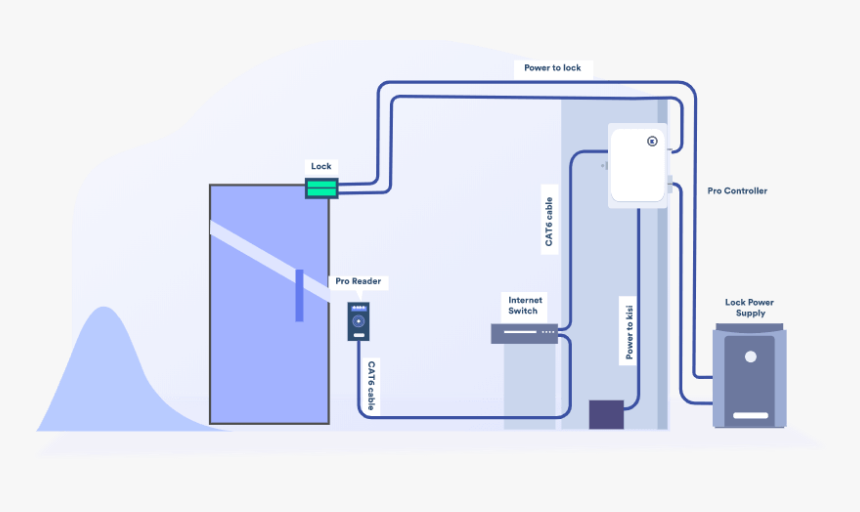
Magnetic Door Lock Wiring Diagram Pdf Hd Png Download Kindpng
1a Determine proper magnet orientation.

Magnetic door lock wiring diagram pdf. Ensure the electromagnetic lock is set for the correct voltage. MAGNETIC DOOR LOCKS MIR6S MIR6B Mircom reserves the right to make changes at any time without notice in prices colours materials components equipment specifications and models and also to discontinue models. The magnet is fitted with a metal oxide varistor to.
GTOs low voltage 2000XL 3000XL 4000XL SL1000 and SL2000 operators do not have a NORMALLY CLOSED. Wiring diagram Parts diagram 3 NOTE. The magnet is fitted with a metal oxide varistor to.
Use the template diagram installation instructions included with the DM62 Magnalock assembly. PINSTALLATION INSTElectromagnetic LocksEXCELINST-E600vsd REV A3 05-18 Page 1 Any suggestions or comments to this instruction or. The best location to install the electromagnetic locks is on the inside of the doors that are being secured with the wiring concealed in the frame to prevent tampering with the unit.
IP Pro IP Pro Plus. 480A2U 480O2U. An inswing mounting kit optional can be used when mounting on the hinge side of the door.
Check for proper voltage at the electromagnetic locks input. When EPS signal is on the door is free to open. Remove screws wiring cover and end blocks.
This delayed Egress locking systems principal application is for secure locking and delayed release of perimeter and emergency exit doors. Sample Wire Diagrams. Magnet End Block with screw holes End Block b.
Remove any diode installed across the magnet for spike suppression. OR Double Door Locks should be installed with wiring covers in the middle so the magnet in one of the locks must be reoriented. Push Plates Panels.
OR 1b Reorient magnet if necessary. Magnetic Lock wiring Instructions 110 V AC Switch or Solid State Switching Device 12 or 24 VDC. Ensure the electromagnetic lock is set for the correct voltage.
Installation Select door type from the following pages use the instructions on each page. The E600 Series magnetic lock is mounted to the underside of the header on the stop side of the door. Magnetic Door Lock Wiring Diagram Pdf Hd Png Download Kindpng Repair Guides Wheatstone Bridge Circuit Diagram Tradeoficcom Librar 5 Wire Actuator Diagram Wiring Diagram Var 1981 Corvette Power Door Lock Wiring Wiring Diagram Ac Range Rover Alarm And Remote Lock.
Settings 1 and 3 are used in fire doors connected to EPS. GTOs GP-Series SL050 SL100 SW050 and SW100 operators are Magnetic Lock ready with a NORMALLY CLOSED contact Lock Terminal. This lock is rated at 1200 pounds holding force and is supplied with a kit of fixing brackets armature plate.
1a Determine proper magnet orientation. MAGNETIC LOCK WIRING INSTRUCTIONS MODELS WITH BOND SENSOR AND DOOR STATUS SENSOR 600LB 600DLB 1200LB 1200D To remove the header plate it may be necessary to remove the wiring compartment screw. 480A1U 480O1U.
The mounting diagram measurement and marking placement are critical. - WIRING INSTRUCTIONS Magnetic locks wired in parallel with a separate button controlling each magnet We suggest using a IN4005 diode inline magnets wired in parallel Power Supply for fail safe strikes and magnetic locks should be DC. From the outside using Allen wrench which is included in each lock delivery.
Single Door Electric Latch Retraction. Check for proper voltage at the electromagnetic locks input. Traditional Power Supply x ELR.
Remove any diode installed across the magnet for spike suppression. If low determine if the correct wire gauge is being used to prevent excessive voltage drop. Electro-magnetic door locks are the most convenient and effective way to achieve secure access control.
If low determine if the correct wire gauge is being used to prevent excessive voltage drop. The features to consideration during the installation procedure. Do not install a diode in parallel with the electromagnetic locks as this may cause a delay when releasing the door as well as cause residual magnetism.
The mounting diagram is NOT a scaled template. Wiring Cover Magnet LHR Door - Shown from Exterior Wiring Cover Magnet RHR Door - Shown from Exterior Magnet should be placed opposite of door hinges. Wiring Diagram Accessories Connector cables Price Security fittings Price.
This allows the lock to achieve its maximum holding strength. Magnetic Gate Lock Kit DoorKing Part Numbers 1216-080 1216-081 It is essential that the surfaces of the armature and the magnetic lock seat perfectly to one another when the gate is in the closed position. If this is not available you may use an AC power source and wire inline a Full Wave Bridge rectifier.
Position the Magnalock centered between the doors. Single Door Electric Strike. 480 Push Plates Actuators Touch Panels.
INSTALLATION AND WIRING INSTRUCTIONS FOR ROFU 8011-004 Delayed Egress Method The ROFU 8011-004 Delayed Egress Magnetic Lock Assembly is designed to comply with the NFPA 101 Life Safety Code. Single Door Magnetic Lock. Single Door Wiring Cover Magnet LHR Door - Shown from Exterior Wiring Cover Magnet RHR Door - Shown from Exterior Magnet should be placed opposite of door hinges.
It is critical the armature is securely fastened to the gate.

Magnetic Door Lock Wiring Diagram Schematic Diagram Pictures Guide 2020
Access Control Systems Australia Access Control System Access Control Wiring Diagram

Home Theater Speaker Wiring Diagram Wiring Diagram Access Control System Security Camera Wiring Diagram

Universal Power Door Lock Wiring Diagram Power Lock

Wiring Diagram For Central Locking Kit

Central Lock Wiring Diagram Toyota

Power Lock Wiring Diagram Power Lock

18 Electrical Door Interlock Wiring Diagram Wiring Diagram Wiringg Net Wiring Diagram Door Locks Magnetic Door Lock

18 Electrical Door Interlock Wiring Diagram Wiring Diagram Wiringg Net Wiring Diagram Entry Doors Diagram
