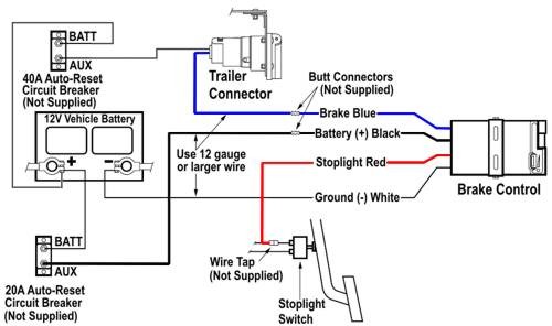
Connect the RED power wire of the brake control unit to the BLACK wire and the BLUE trailer brake wire of the brake control unit to the BLUE wire with scotch locks supplied. Standard 4-wire hookup is compatible with virtually all 12-volt negative ground tow vehicles.
Brakemate Mt Wiring Diagram - If you're searching for picture and video information related to the key word you've come to visit the right blog. Our site gives you suggestions for viewing the maximum quality video and picture content, hunt and locate more informative video articles and graphics that fit your interests. includes one of thousands of video collections from several sources, particularly Youtube, so we recommend this video for you to see. It is also possible to contribute to supporting this site by sharing videos and graphics that you enjoy on this blog on your social media accounts such as Facebook and Instagram or tell your closest friends share your experiences concerning the ease of access to downloads and the information that you get on this site. This blog is for them to visit this website.

Brakemate Mt Installation Fasrmystery
Apache Rtr 160 Wiring Diagram.
Brakemate mt wiring diagram. The black wire on the controller will attach to the 12-volt positive line in the harness and the blue wire will connect to the output line in the harness that sends the signal to the trailer coupler. Trailer Parts Superstore offers this DRAW-TITE wiring diagram for general reference only. This wire is called the 12 volt hot lead The second wire blue runs to the brake controller to supply power to the trailer brakes.
Brakemate has 4 wires and the wiring harmess has 5 wires. 1986 Honda Gl 1200 Aspencade Gold Wing Wiring Diagram. BRAKEMATE MT CONTROLLER MANUAL READ ONLINE.
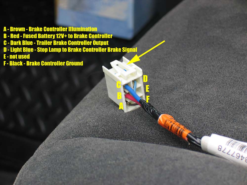
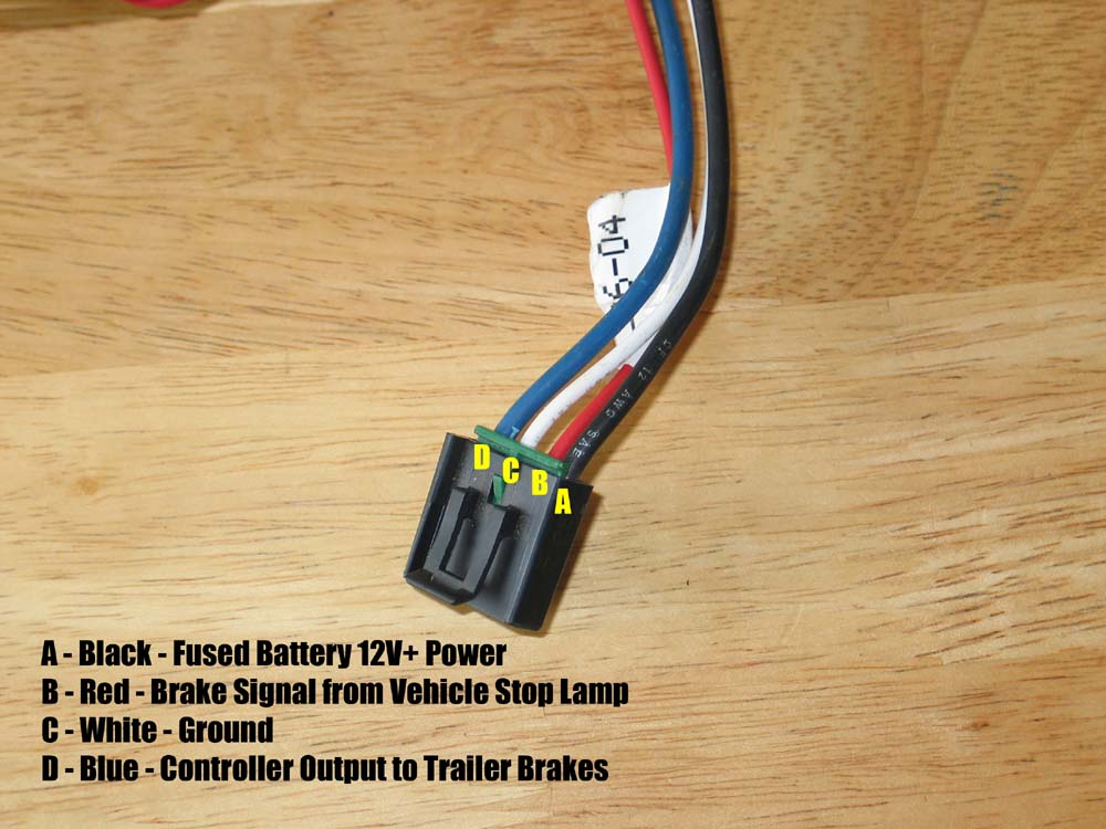
Wiring legend for the Brakemate diagram show. The friction between the brake pads and the drums slows the vehicle and converts kinetic energy for our purposes the energy moving the trailer into heat. 6 Pin Jst Test Connector To Rs232 Wiring Diagram.
Brakumanteeu detecteren als het een scam frauduleuze of is geïnfecteerd met malware phishing fraude en spam activiteit als je. 4 wires Black Wire positive battery - White wire negative battery Red wire cold side of stoplight switch Blue wire brake output to trailer The wiring. Split the BLUEBLACK 2 strand wire down the middle.
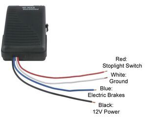
MACHINE ELECTRICAL SYSTEM 5 inqerht Singerlight and Three-Pin Terminal D lack ro Outlet Ell used with Singer Machine. The blue wires carries the brake output from the controller the white wire is the ground the black wire supplies 12 Volt power and the red wire is tied into the vehicle brake wiring. The wires exiting the rear of your controller serve the following functions.
Jan 27 Need some help with the brake box wiring. Problem with Schecter Electronics Discussion in Pickups Electronics BG started by but check the wiring against a diagram. You need to make sure the blue wire is getting power under the hood if it is and it still doesnt read at the rear it is broke in 2 somewhere along the way or not in the plug good.
Trailer Brake Control Wiring Diagram. Brakemate has 4 wires and the wiring harmess has 5 wires. You could send a full jolt of electricity back to the brakes and theyd respond.
Stihl 028 Av Super Parts Diagram Pdf. Sep 08 The guy I exchanged emails with at Schecter was helpful but didnt have the wiring diagram. Connect the WHITE wire of the brake control unit to the ground on vehicle body.
Referring to that diagram I used a 2N PNP transistor and a uF capacitor and a 75k. 12-2 Duplex Wire 30 Amp Circuit Breaker and Attaching Terminals. The job of the brake controller is to send the appropriate amount of current flow back to the brakes.
Wiring Diagram of BRS Sewing L amp 10 Canttder Unit To Motor Puey End Motor Wiring Of BY Family Sewing Machine C. Parts Diagram for Benwil FP12G. 12-2 Duplex Wire 20 Amp Circuit Breaker and Attaching Terminals.
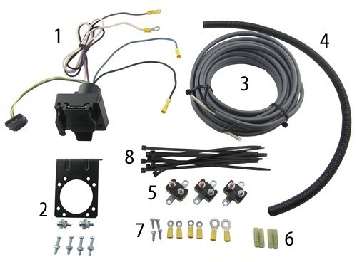
Wiring Kit for 6 to 8 Brake Control Systems Includes 25 ft. I thought that it might be fun to salvage the electric eye sensors for some other purpose. Connect the ground wire to the white wire on controller will attach to the ground on the harness.
TECHNOLOGIES Irwin Vise-Grip WILTON Graco Bend-Pak Clore Bosch CLC MASTERCOOL Rolair Bend Pak GTI Wheel-A-Matic Ranger Sice Aircom MT-RSR. Lifan Mc-18 Wiring Diagram. Trailer brake controller wiring color codeaccutrac brake controller wiring diagram brake controller wiring kit.
Then mount the controller bracket in the desired postion. Brakumanteeu is brakumanteeu veilig. Wiring legend for the Brakemate diagram show.
I have my Brakemate MT box from my previous truck and the wiring harness for the new truck. Brakemate Mt Wiring Diagram. 6 x 38 Screws.
Wiring Kit for 2 to 4 Brake Control Systems Includes 25 ft. Elkay Solenoid Valve S-45rv Wiring Diagram. Flo-Dynamics BrakeMate Jr Parts.
Mccarty Vintage Prs Pickup Wiring Diagram. If the wiring adapter you have is an aftermarket harness it should wire up color for. Schecter Wiring Diagrams - schecter I have a Schecter Diamond Series Stiletto Elite-4 with EMG HZ pickups.
Consult your tow vehicle owners manual for specific wiring information. The red wire on the controller will attach to the lead from the brake light switch. The mount the trailer connector near the hitch on the rear of the vehicle.
CAUTION Drilling or use of longer screws may damage unit. Controleer brakumanteeu website is een scam of een beveiligde website. I have my Brakemate MT box from my previous truck and the wiring harness for the new truck.
When the main plastic gear stripped I had to replace my garage door opener. Ive researched it quite a bit and I. First disconnect the positive battery before anything.
Need some help with the brake box wiring. If there is no bracket then mount the controller and remove to make connections simpler. Brakemate has 4 wires and the wiring harmess has 5 wires.
You can find Schecter wiring diagrams on their website. BRAKEMATE MT CONTROLLER MANUAL DOWNLOAD. Philips Bodine Emergency B100 Wiring Diagram.
4 wires Black Wire positive battery - White wire negative battery Red wire cold side of stoplight. Flo-Dynamics Coolant Service Equipment. Mar 15 HELP.
Parts Diagram for Benwil BWO9 BWO9L BWO9H. Those wires go in parallel to two connectors on the opener. This wire is called the brake wire The third wire.
The first wire black runs to the vehicles battery to supply power to the trailer connector.

Pin On Wiring Diagram
Billavista Com Atv Tech Article By Billavista
Billavista Com Trailer Brake Controller Tech Article By Billavista
Brake Controller Installation Starting From Scratch Etrailer Com

Brakemate Mt Installation Fasrmystery
Brake Controller Installation Starting From Scratch Etrailer Com

Pin On Electrical Wiring Diagram

Pin On Ford S Wiring
Brake Controller Installation Starting From Scratch Etrailer Com
