Rear left up Blue. It shows the components of the circuit as efficient types and additionally the energy along with indicator web links in between the gadgets.
Avs 7 Switch Box Wiring Diagram - If you're looking for picture and video information related to the keyword you have come to pay a visit to the ideal site. Our site gives you hints for seeing the highest quality video and image content, hunt and find more informative video articles and images that match your interests. includes one of tens of thousands of video collections from several sources, particularly Youtube, so we recommend this movie that you view. It is also possible to bring about supporting this website by sharing videos and graphics that you enjoy on this blog on your social networking accounts such as Facebook and Instagram or tell your closest friends share your experiences concerning the ease of access to downloads and the information you get on this site. This site is for them to stop by this site.

Battery And Wiring 24 Volt Part 2 Of 2 As Viewed From R H Side Of Machine 9m1305 8m7677 Lamp 7k9011 Harness And 3k1650 Switch Parts Are Shown On Pages 47 50b And 52b See
Range of avs 7 switch box wiring diagram wires representation.

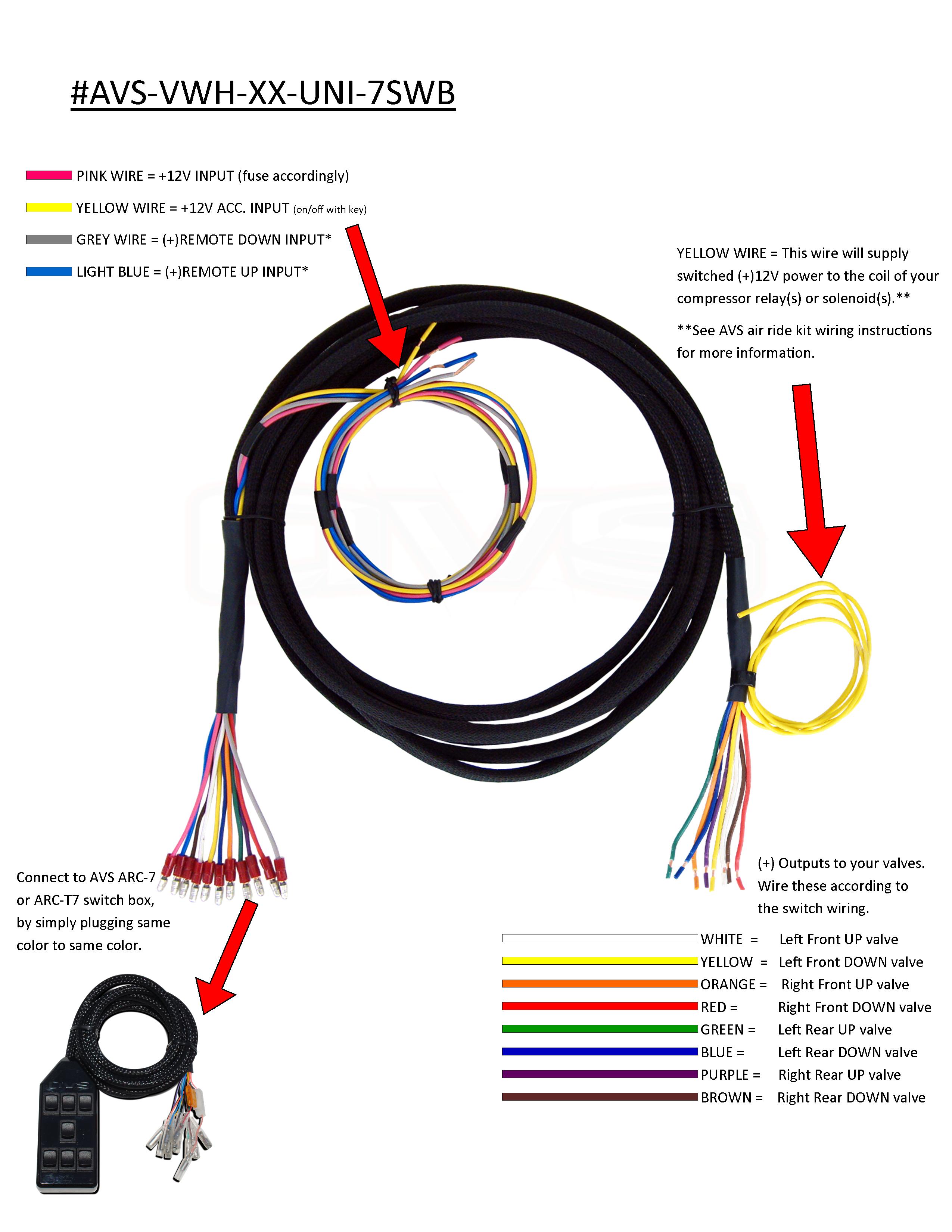
Avs 7 switch box wiring diagram. Front right up Red. Pink goes to battery. Avs Valve Wiring Harness 10 15 20 Universal To Avs 7 Switch Box Help i need the wiring diagram for air ride solenoids to ten swtich box.
Here are a couple of diagrams i made up for one of my friends who wanted to get into air ride but didnt quite understand all the basics. Gray is for if you have an alarm or remote you can. From those connectors I always run 18 gauge wire out to the valves and Ive never had a fire- yetFWIW Home Depot carries a kick- wire for valves- 18 gauge 4 conductor sound and security wire.
If you are not. Avs Switch Box Wiring Diagram wiring diagram is a simplified agreeable pictorial representation of an electrical circuit. 5-amp in-line fuse If you have one of the following valves.
Front left down Orange. Avs 9 Switch Box Wiring Diagram. Air Ride Switch Box Wiring Diagram.
Rear right down Did this help. AVS 7-SWITCH BOX Brown - - - Right Rear Dump Purple - - - Right Rear Fill Blue - - - Left Rear Dump Green - - - Left Rear Fill Red - - - Right Front Dump Orange - - - Right Front Fill Yellow - - - Left Front Dump White - - - Left Front Fill Pink - - - 12v Power Grey - - - AUX All Dump Light Blue - - - AUX All Fill STANDARD ORIENTATION AVS SWITCH BOX. Rear right up Brown.
Overall length of 8 feet. On Avs Switch Box Wiring Diagram. The AVS box has a wiring coloring diagram showing what it controls.
It works with a 2 pump 3 pump or 4 pump setup. Home AVS Air Suspension AVS Switch Boxes ARC-7 Series ARC-7 AVS VALVE WIRING HARNESS 10 15 20 - ACCUAIR VU4. Air ride switch wiring help lots of switches so im building a air system for my rat rod on a 68 c10 chassis.
Avs Valve Wiring Harness 10 15 20 Universal To Avs 7 Switch Box. I was curious as to getting a wiring diagram on my valve box and what each wire actually controls. 1990 Ford Ranger Radio Wiring Diagram.
A circuitry diagram is a sleek common photo symbol of an electric circuit. It works with a 2 pump 3 pump or 4 pump setup. The wiring from the AVS box is small but Ive never seen one fail.
There are 10 total switches. Wire colors match up to the AVS 7-Switch Box wiring diagram. Power input 10 AMP fuse White.
The given circuit is a basic switchboard wiring for a light switch and 3 pin socket with control switch. Front right down Green. 2 May 13 2013.
And im working on a 3rd diagram showing switch wiring that overlays with the valve diagram. The run from the box to the bullet connectors is pretty short so it should be fine. Front left up Yellow.
It shows the components of the circuit as simplified shapes and the capacity and signal friends amongst the devices. Avs switch box wiring diagram avs 9 switch box wiring diagram avs 3 switch box wiring diagram avs 7 switch box wiring diagramfor ssr 110 atv wiring diagram 1998 dodge ram 1500 stereo wiring diagram smittybilt xrc 10 winch wiring diagram er diagram dbms ppt labeled diagram of catnip plant 5jlsdgfuer4de. Rear left down Purple.
Avs 7 Switch Box Wiring Diagram wiring diagram is a simplified enjoyable pictorial representation of an electrical circuit. Avs 9 Switch Box Wiring Diagram studebaker info rjtechdec2017p2g htmlStudebaker Avanti Avanti II Resource Website All free informatio. Air ride suspension switch box.
California Three Way Switch Diagram. Cord Length Approximately 7-ft 12-V inputs for your Remote Up Light Blue and Dump Gray options. This air suspension controller has a beautiful transparent red exterior with 7 rocker switches to control your vehicles air suspension.
Here are a couple of diagrams i made up for one of my friends who wanted to get into air ride but didnt quite understand all the basics. Source black 9 switch series rocker avs and avs switch box wiring diagram. AVS 7-SWITCH BOX REVERSE ORIENTATION White - - - Right Rear Dump Yellow - - - Right Rear Fill Orange - - - Left Rear Dump Red - - - Left Rear Fill Green - - - Right Front Dump Blue - - - Right Front Fill Purple - - - Left Front Dump Brown - - - Left Front Fill Pink - - - 12v Power Grey - - - AUX All Dump Light Blue - - - AUX All Fill AVS SWITCH BOX.
November 13 2018 November 13 2018. I Just picked up an AVS-7 rocker switch box that has the blue accent lighting inside and ive got the big red ride tech valvesthe 7rocker isnt installed yet. Avs Switch Box Wiring Diagram.
AVS Switch Box 7-switch red. Ge Gas Cooktop Parts. Double Door Refrigerator Wiring Diagram.
Accuair VX4 Accuair VU4 Accuair Endo-VT or CVT Slam SV-8C EVOLVE Manifold or AVS Manifold. Female Bullet Connectors are pre-assembled on switch box for easy installation. It shows the components of the circuit as simplified shapes and the gift and signal connections surrounded by the devices.
When it comes to maneuvering your air suspension you should always use a controller that is easy to use. The power ground and auxiliary wires are 10 feet long. Wow what a way to compliment the interior in your custom car or custom truck.

Battery And Wiring 24 Volt Part 2 Of 2 As Viewed From R H Side Of Machine 9m1305 8m7677 Lamp 7k9011 Harness And 3k1650 Switch Parts Are Shown On Pages 47 50b And 52b See

10 Valve To Avs 7 Switch Box Avs Valve Wiring Harness China Accuair Suspension Valve Air Suspension Manifold Made In China Com
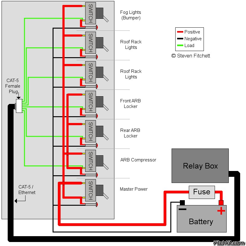
Diagram 3 Switch Box Wiring Diagram Full Version Hd Quality Wiring Diagram Avdiagrams Fanofellini It
Diagram Bmw 2 Wiring Diagram Full Version Hd Quality Wiring Diagram Avdiagrams Fanofellini It
Air Ride Switch Box Wiring Diagram

Diagram Gator 625i Wiring Diagram Full Version Hd Quality Wiring Diagram Odiagrami Fanofellini It

Diagram Code Alarm Wiring Diagrams Full Version Hd Quality Wiring Diagrams Avdiagrams Fanofellini It
Diagram 1971 Chevelle Wiper Wiring Diagram Full Version Hd Quality Wiring Diagram Avdiagrams Fanofellini It

Diagram Mazda Biante Wiring Diagram Full Version Hd Quality Wiring Diagram Avdiagrams Fanofellini It
