USB cable is regarded as a serial bus. The majority of them use USB cable.
Zero Delay Usb Encoder Wiring Diagram - If you're looking for picture and video information linked to the key word you have come to visit the right blog. Our website gives you suggestions for seeing the highest quality video and image content, search and find more informative video articles and graphics that fit your interests. includes one of thousands of video collections from several sources, particularly Youtube, so we recommend this video that you view. It is also possible to bring about supporting this site by sharing videos and graphics that you like on this site on your social media accounts such as Facebook and Instagram or tell your closest friends share your experiences about the ease of access to downloads and the information you get on this site. This site is for them to stop by this site.
Zero Delay Usb Encoder Retropie Forum
Construction USB Cable According to USB Wiring Diagram.

Zero delay usb encoder wiring diagram. The red one is for positive cable with DC ability of 5 volts. According to 45 seconds of research it looks like the ZD is a gamepad encoder not a keyboard encoder. Theyre named as D- and D.
Suzo Happ Competition Joysticks 5 pin ribbon cable for Japanese style Joysticks ie. Sj Jx Arcade Usb Encoder Pc Ps3 Android Ps3 Encoder Power 5v Us 10 26 5 Off Zero Delay Usb Encoder To Pc Games For Arcade Sanwa Joystick Buttons Kits Parts Use On 5 Pin Roker And 2 8mm Buttons Interface In X Arcade Wiring Diagram Jamma To Usb Wiring Diagram Usb Zero. This Zero Delay comes with standard 187 and 250 wiring that will both power and illuminated your arcade push buttons.
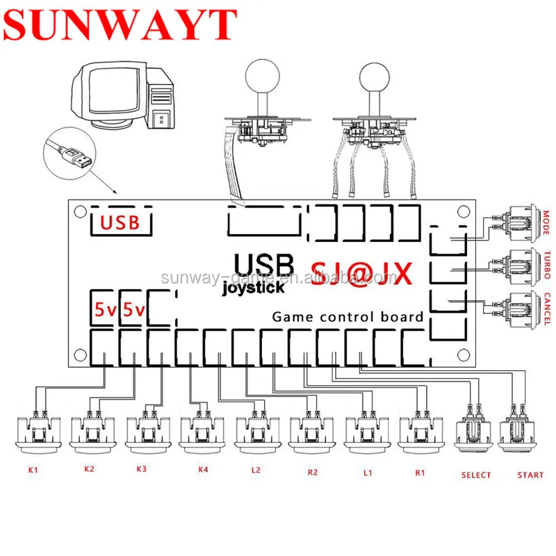
Or in case a button arrives broken. The cable is made up of four threaded wires. Installation is very straight forward - simply connect your joystick and buttons to the included wiring and plug into the PCB plug the USB cable into your PS3PCLaptop or Raspberry Pi map your buttons in either RetroPi or Mame and thats it.
October 26 2013 102737 am Hey I actually got this sorted out the ground wire on the USB Jack was frayed and down to only one stand of wire. Typically it utilizes black green red and white cable colors. At the junction of the 2 resistors the voltage will be 25 Volts.
The red one is to get positive cable with DC power of 5 volts. Usb Encoder Wiring Diagram. 3 Aug 2016 1601.
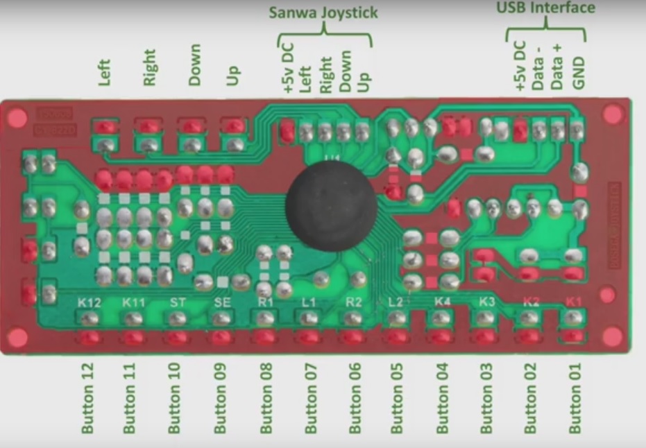
10x red and black joystickbutton connectors. A USB arcade encoder that powers 5v LEDs. Zero Delay USB Interface - Part 2.
Meanwhile the remaining two wires are for information signals. Posted by 1 year ago. One encoder per player.
Black wire serves as ground just like in every other apparatus. Need Help with 2 Zero Delay USB encoders working. According to Usb Encoder Wiring Diagram you will find only four wires used inside the cable.
The manufacturers save money on the resistors by linking them all together. Two wires GND and 5v are especially for electricity. The cable may be used to transfer information from 1.
We are going to wire up the Joystick first so grab that and the ribbon cable. Zero Delay USB Interface - Part 2. Typically it utilizes black black red and white wire colors.
The red one is for positive cable with DC ability of 5 liter. I purchased a 2-player Arcade Kt. One LED button of 14 wouldnt light up.
Notes on the 3rd party knock off Chinese joystick and buttons. Usb Encoder Wiring Diagram There are a number of kinds of electronics on the market. Usually when you search for the zero delay controllers they will be paired up with a joystick set that you will normally see below.
Lurker said in Zero Delay USB Encoder. Help with USB Zero Delay Encoder over long wire Reply 10 on. Mix and Match the joystick wiring for your Zero Delay encoder187 connections for American Style Joysticks ie.
Zero Delay Usb Encoder Wiring Diagram. USB Wiring Diagram. A USB male A cable to 4-pin Molex connector.
- all of the junctions of R1R2 R3R4 R5R6 R7R8 are all linked together on the rear of the PCB by very fine tracks. The encoder board. JLF-TP-8YT joysticks Click on the image below for the full size wiring diagram.
Support RMC on Patreon. Mach3 Usb Controller Setup Wiring And Configuration Part 1. Usb Cnc Controller Mach3 4 Axis 100khz Interface Board Mk1 Cnc.
They are wired in series between the 5V and Zero volts pin of the USB connection from the PC. Typically it utilizes black green red and white cable colors. Lurker said in Zero Delay USB Encoder.
That happened to me. Zero Delay Usb Interface Part 2 The Pcb Youtube. The PCB - YouTube.
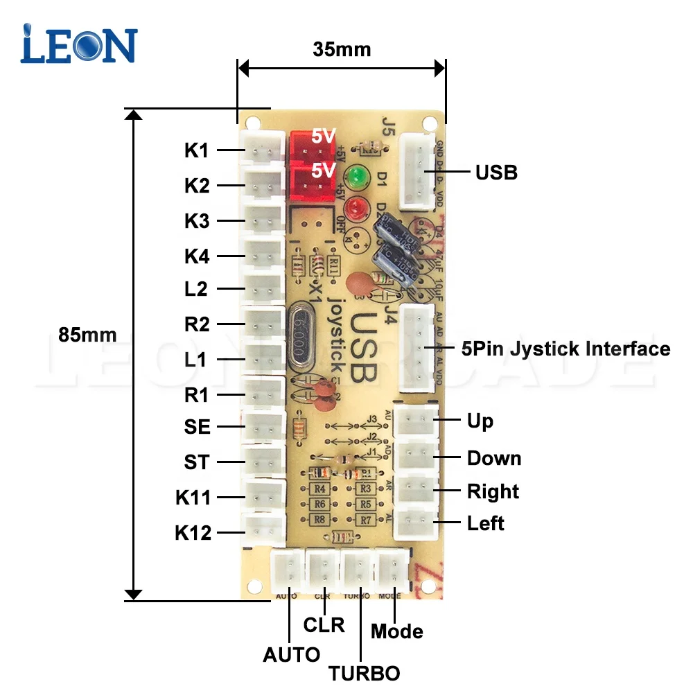
So youve just received your Zero Delay Arcade USB Encoder and its time to wire it up. Fortunately a friend of me could repair it by soldering. Zero Delay Usb Joystick Encoder S Config.
Plug one end of the ribbon cable into the joystick port then plug the other end onto the 5 pins on the. Black cable serves as floor just like in every other device. According to Usb Encoder Wiring Diagram there are just four wires used in the cable.
Start by getting the USB Encoder PCB board and take note of the connections. Black wire serves as ground just like in any other device. 6 Axis Cnc Mach3 Engraving Machine Interface Breakout Board Usb.
Need Help with 2 Zero Delay USB encoders working. USB Encoder Joystick without cable The Zero delay is the most cost effective encoder option available. An extra button in case one breaks is a good answer too.
Oleh admin Juli 14 2020 Posting Komentar. With just that much info I would think that if it is detected as a gamepad it would be just plug and play. Rbaker Its a Zero Delay encoder post thread title.
According to Usb Encoder Wiring Diagram you will find only four wires used from the cable. Buildyourcnc Mach3 Usb Interface Board. I am new to the world of RetroPie and thought a fun project would be to build a 2-player arcade controller with the Pie built in.
Zero Delay Usb Encoder True Analog Joystick Modification 5 Steps Instructables
Zero Delay Usb Interface Part 2 The Pcb Youtube
Zero Delay Usb Joystick Encoder S Config
Zero Delay Usb Encoder Arcade Pc 5pin Joystick Wiring Happ Buttons Cable Games
Zero Delay Arkade Usb Joystick Pc Ke Jamma Kontrol Usb Untuk Jamma Mame Multicade Keyboard Usb Encoder Buy Zero Delay Arcade Usb Encoder Pc Zero Delay Arcade Usb Encoder Usb Keyboard Encoder Product
Zero Delay Has Two Red 2 Pin 5v Connectors How To Connect 10 Led Buttons
Wiring A Happ Joystick To A Zero Delay Encoder
Zero Delay Usb Encoder To Pc Arcade Joystick Diy Kit Controller Part Mame Games 5pin Cable 10x 3pin 2 8mm Wire Coin Operated Games Aliexpress
Video Tutorial 100 Zero Delay Usb Encoder To Pc Rasberry Pi Arcade Cabinet Diy Kit Arcade Stick Arcade Game Diy Part Buy Zero Delay Arcade Usb Encoder Usb Joystick Encoder Arcade Controller Product


