Look for a hot while ignition on wire to run to the terminal. Currently the water pump and electric fan and grounded to the cylinder head and the the first diagram is their electric fan relay harness kit.
Proform Electric Fan Wiring Diagram - If you're searching for video and picture information related to the keyword you've come to pay a visit to the right blog. Our website provides you with suggestions for seeing the highest quality video and picture content, search and find more enlightening video articles and graphics that fit your interests. comprises one of tens of thousands of video collections from various sources, especially Youtube, therefore we recommend this video for you to view. This site is for them to stop by this website.
Why Didn T I Convert To A Taurus Fan Sooner Page 2 Ih8mud Forum
Proform provides a very simple easy-to-follow installation guide.

Proform electric fan wiring diagram. Positive battery to positive Fan lead. Nothing here should be confused with the latest generation of PWM VARIABLE SPEED CONTROLLERS which have. Often epoch it is no more complicated than the wiring of a spacious fixture.
However this will cause the fan to run even when the car is off if it is hot. You may free up 1 or 2 but this fan isnt for racing so you shouldnt be looking in this department for power but for cooling that beastly street machine. Electric water pumps are nothing new in the world of high-performance and even street-going engines.
Electric fan should start immediately. WIRING Red Loose wire. Housed in a weather and temperature-resistant billet aluminum case this Proform Digital Fan Controller mounts under the hood and contains a simple 6-wire harness that connects the battery ignition ground sensor probe and up to two fans.
Replace your stock cooling fan setup with an efficient and powerful direct-fit electric fan from Proform. As once any electrical wiring create clear all wire links are made securely subsequently the proper size wire nuts that they are not drifting and that no copper strands are showing. 30 Lovely Proform Electric Fan Wiring Diagram- Wiring a ceiling fan is surprisingly simple.
Another thing your not going to gain horsepower switching to electric fan. Proform Electric Fan Wiring Diagram How To Install And Wire A Flex Flex A Lite Wiring Diagram Info Outstanding Electric Fan At Flex A How To Wire An Electric. Air conditioning relay activates fan when AC is turned on.
If fan started reattach the Green wire to the proper wire on the AC clutch or Manual Switch. The B is the high current plug just powers the relay. Terminal on the battery.
Using the Blue Butt Connector provided attach the other end of the loose Red wire to the positive lead on the electric fan. 3Ø WIRING DIAGRAMS 1Ø WIRING DIAGRAMS Diagram ER9 M 3 1 5 9 3 7 11 Low Speed High Speed U1 V1 W1 W2 U2 V2 TK TK Thermal Overloads TWO SPEED STARDELTA MOTOR Switch M 3 0-10V 20V 415V AC 4-20mA Outp uts Diagram IC2 M 1 240V AC 0-10V Outp ut Diagram IC3 M 1 0-10V 4-20mA 240V AC Outp uts These diagrams are current at the time of publication. Suggested Electric Fan Wiring Diagrams PAGE 1 These diagrams show the use of relays ONOFF sensors ONOFF switches and ONOFF fan controllers.
Proform is out to make the conversion as easy as possible with their all new 2 nd generation digital variable speed electric fan controller. The first part of the installation is to install the electric fan to your radiator and remove the mechanical fan. Bolt one on today with the sturdy supplied brackets.
Connect the other end of the wire to the C terminal of the control box. A relay kit our part number CCFKRL will include everything you need to properly wire up your electric cooling fans with the exception of additional wiring needed to complete all of the circuits. Using the Yellow Ring Terminal provided attach one end of the red loose wire to the vehicle positive terminal on the battery.
Wire provided in the kit. Capable of commanding one or two fans this units digital display makes for an easy and versatile setup. The kit includes two brass temperature sensing probes one for pushing between the cooling fins on.
TROUBLE SHOOTING QA Diagram 3 Relay Red Yellow Black Green To 12V Switched Ignition To Ground -Chassis Override Circuit Loose Red Wire Positive Battery Negative - Fan Wire Fan. Download wiring diagram PDF format. On Proform Electric Water Pump Wiring Diagram.
1 Electric fan 2500cfm minimum. I had my setup like this and just ran battery into the spade. Equipped with an adjustable 160-240 degree F thermostat and heavy-duty motor these fan assemblies provide a substantial increase of surface area cooling to improve engine performance.
We ran power directly to the battery and to the fan a negative wire to the body the wire to the radiator temperature probe and a final wire to the 12-volt ignition so that the fan could operate. Proform Mustang Electric Fan Kit 86-93 50. Architectural wiring diagrams perform the approximate locations and interconnections of receptacles lighting and long-lasting electrical services in a building.
Interconnecting wire routes may be shown approximately where particular receptacles or fixtures must be on a common circuit. Here is the fan specs. Adjust thermostat to desired temperature within.
With the wire and 3-way connector provided splice into the AC clutch positive wire. Below is a diagram I made to show how I went about it. Proform electric fan wiring diagram unique electric fan wiring.
Diagram Jeep Cherokee Cooling Fan Relay Wiring Full 6daff Volvo 740 Ignition Switch Wiring Diagram Digital Resources Gm Ecm Wiring Diagrams 2006 Today Schematic Diagram. Electrical Proform Electric Fan Install With Pics Mustang. Depending on what relay you use you may want to double check pins 86 and 85 if youre using a bosch type you could be powering 87 or 87a depending on what polarity is being used on pins 8586.
Electrical Proform Electric Fan Install With Pics Stangnet

Electric Fan Wiring Diagram Also Here Is The Wiring Diagram I Used For Wiring The Electric Fan I Too Us Electric Radiator Fan Radiator Fan Electric Cooling Fan

Dual Cooling Fan Wiring Diagram Electric Cooling Fan Radiator Fan Electric Cooling

18 Electric Stand Fan Wiring Diagramelectric Stand Fan Wiring Diagram Wiring Diagram Wiringg Net Ceiling Fan Switch Desk Fan Stand Fan
Electrical Proform Electric Fan Install With Pics Stangnet

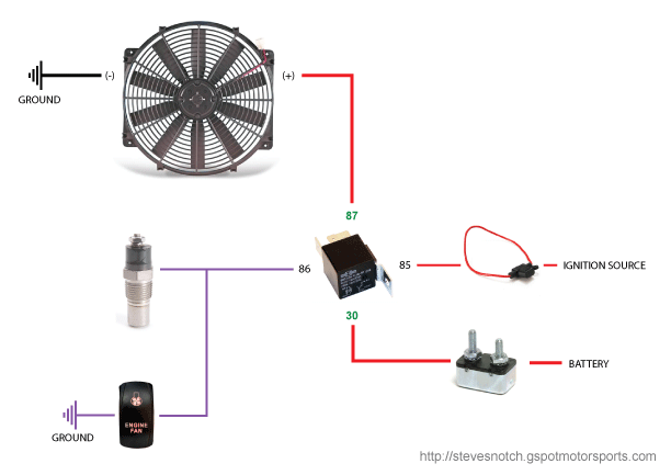
77 Lovely Electric Fan Relay Wiring Diagram Radiator Fan Electric Cooling Fan Wiring Diagram
Electric Fan Install How To Fox Mustang Foxstang Com
Electric Fan Relay Wiring Diagram Electrical Circuit Diagram Electric Fan Wiring Diagram
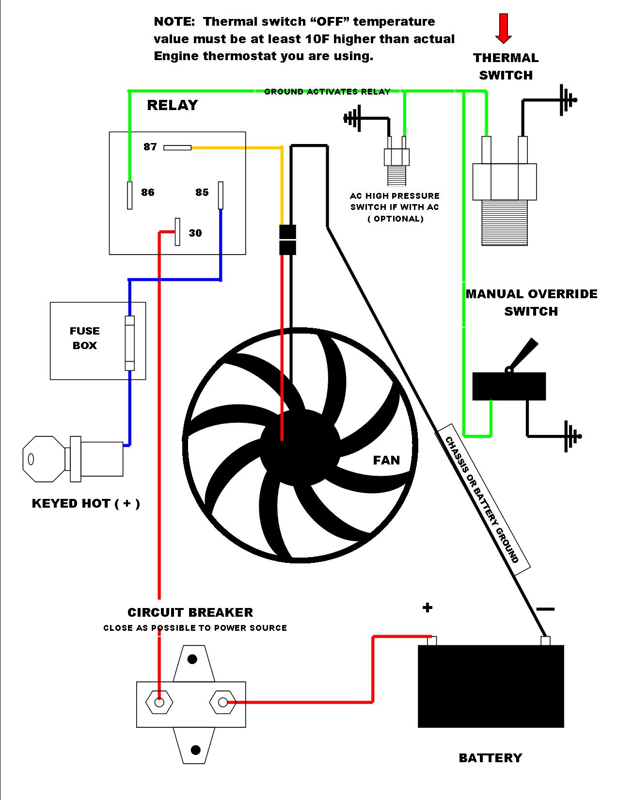
Diagram 3 Wire Fan Diagram Full Version Hd Quality Fan Diagram Avdiagrams Fanofellini It
