The MG TDTF Wiring Looms. They should be hooked up in parallel.
Mg Tf Horn Wiring Diagram - If you're searching for picture and video information related to the key word you've come to pay a visit to the right site. Our site gives you hints for seeing the highest quality video and picture content, search and find more informative video articles and graphics that fit your interests. includes one of thousands of video collections from various sources, especially Youtube, therefore we recommend this movie that you view. It is also possible to contribute to supporting this website by sharing videos and images that you like on this site on your social networking accounts such as Facebook and Instagram or tell your closest friends share your experiences concerning the ease of access to downloads and the information that you get on this site. This blog is for them to visit this website.

Wiring Diagram Of Motorcycle Alarm System Http Bookingritzcarlton Info Wiring Diagram Of Motorcycle Ala Ceiling Fan Wiring Ceiling Fan Switch Wiring Diagram
Diagram shows fuse 1 as the most RIGHT fuse when facing the car from the front Fuse No Amps Function 1 15 Stop lights horn 2 15 Cooling fan 3 15 Air conditioning fan 4 10 Hazard Warning lights 5 15 Central door locking alarm 6 30 EMS 7 30 EMS CD - Electrical Circuits Diagram shows fuse 1 as the most LEFT fuse when facing the car from the front.

Mg tf horn wiring diagram. If you own a MG TDTF you probably know the car is under-fused by modern car standards. Originally the TC horn had been wired through the fuse to the A1 terminal through the series winding in the regulator to the A terminal then through the ammeter to the battery. Hystorical and well known Dieter web site mgfcarde for MGF.
The first connects posts A1 A2 of the panel and protects the horn circuit. MG TD MG TF Magnette MGA Twin cam MGB MGBGT MGC MGC GT MG Midget Sprite and other MG models from British car spares company LBCarCo. Several web sites provides diagrams.
The first section from Barrie Jones contains information about the wiring color codes used inside the harnesses. MG TD Wiring Diagram parts 356-040 356-140 356-050 356-150 357-070 357-080 356-278 356-308 357-068 NOTEIt is suggested that the clock be connected to the A2 fused terminal. As mentioned the purple wire going to the stalk is for a live feed to flash the high beams.
Additionally Wiring Diagram provides you with time body in which the projects are to become finished. With a meter check if you have permanent 12V to a good earth. Mg Tf Horn Wiring Diagram November 10 2019 1 Margaret Byrd.
The horns are both fed directly via a purple fused always live circuit. The second fuse connects posts A3 A4 of the panel. On very early TDs with 9-post regulators eliminate the 33 wire from the starter switch to the fuse block.
Joined May 30 2009. The horns can malfunction and sometimes they can be braought back to life by a rap or sharp tap to the horn assembly to unstick the resonantor coil. If you havent yet done so test the horns direct with some cable direct from horn terminal to battery.
I would do as James suggests - check to see whether there is a voltage at the horns. 3 Apr 19 2011. The site also has a link to the colour wiring diagrams heres direct for.
This is in german language httpmg-wikibritische-klassikerdedownloadMGTF_Schaltplaenepdf. You may be able to know precisely once the assignments needs to be finished which makes it easier for you personally to correctly control your time and efforts. You may be able to know precisely once the assignments needs to be finished which makes it easier for you personally to correctly control your time and efforts.
So when the horn was used it would draw current through the ammeter and would pull in the series contacts in the regulator to heat the dynamo up a bit. The electrical diagram for the Mk1 MGF is below - and the MY2000 MGF is very similar. Easy enough to test.
4 Pin Relay Wiring Diagram Horn wiring diagram is a simplified satisfactory pictorial representation of an electrical circuit. The sidelight uses a 501 bulb. MG MGTF Fuse PanelBoard Fuse Symbol Map Related diagrams.
I have attached a wiring diagram that I cleaned up from the original on page 60 in the TF-1500 Operation manual. The TFs headlight unit houses 3 bulbs as follows. This returns to the stalk wiring via the purpleblack and is earthed via the column directly or later via a black wire inside the column switch.
There are only two stock fuses. Simple job which makes a world of difference. The forum software will reduce the resolution but it will probably still be OK.
It shows the components of the circuit as simplified shapes and the capability and signal contacts in the company of the devices. The main beam uses a HB3A bulb - the A on the end is very important. Mgb Wiring Diagram Wiring Library Mg Wiring Diagram.
The mounting bracket bolted to an adjacent threaded hole on the inner wing. I fitted a High tone horn from scrap Metro connecting and soldering the wiring into the existing Low tone horn. It will be all right in the end.
It protects the brake light turn signals if equipped windshield wiper and low fuel warning. Some forum members may have a wiring diagram that is in color to make tracing the wires easier. If no joy Ill check out a wiring diagram 2moz.
The dipped beam uses a H7 bulb. The idea is to split the horn circuit along the lines in the diagram many thanks to Deiters pages for this so that the klaxon operates from the alarm and the main horns from the push butttons. These pages contain detailed information about the wiring looms used in the MGTD and MGTF.
The only proper ground is thru the horn push and 12v power is always on one terminal of each horn each supplied by its own wire from the fuse box. MG MGB Technical - Horn wiring. MG F-TF 2007 Main Engine Fuse BoxBlock Circuit Breaker Diagram MG ZS 2007 Mini Fuse BoxBlock Circuit Breaker Diagram MG ZS 2002 Main Engine Fuse BoxBlock Circuit Breaker Diagram MG TF LE500 2011 Compartment Fuse BoxBlock Circuit Breaker Diagram.
Colors of the wires are number-coded on the diagram. Or visit apptony mg site apttonycouk. Mgb Wiring Diagram Wiring Library Mg Wiring Diagram Additionally Wiring Diagram provides you with time body in which the projects are to become finished.
The second section from Bruce Sharman of Bygone Spares and Restorations describes the loom outer coverings or. All other wiring is identical. If you look at the wiring diagram if either one of the wires on either horn is removed then the other should still blow.

3 Phase Wiring Diagram For House Http Bookingritzcarlton Info 3 Phase Wiring Diagram For House Ceiling Fan Wiring Ceiling Fan Switch Wiring Diagram

Pin On Wiring Diagram
Diagram Atv 1000 Wiring Diagram Full Version Hd Quality Wiring Diagram Avdiagrams Fanofellini It

Pin On Wiring Diagram

Basic Hvac Wiring Diagrams Schematics At Diagram Pdf Wiring Diagram Diagram Diagram Design

2007 Dodge 2500 Radio Wiring Diagram In 2021 Engine Diagram Electrical Wiring Diagram Wiring Diagram

Diagram 1938 Mg Wiring Diagram Full Version Hd Quality Wiring Diagram Avdiagrams Fanofellini It

Navigation Lights Wiring Diagram Hazard Lights Wiring Diagram Navigation Lights
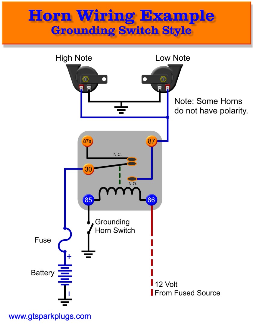
Diagram Older Horn Wiring Diagram Full Version Hd Quality Wiring Diagram Avdiagrams Fanofellini It
