Tz 1693 Copeland Wiring Diagrams Diagram Diagram Copeland Compressors Wiring Diagrams Full Version Hd Quality Rediagram Shiatsupalombini It Emerson Cr22k6me Pf1 111dm Copeland Crk6 Kq Compressor For Air Conditioning Scroll Vacuum Pump Type Spiral स क र ल प सर Climate Technologies India Limited Pune Id 19774294712. Crankcase Heater Location.
Copeland Crankcase Heater Wiring Diagram - If you're searching for video and picture information related to the key word you have come to pay a visit to the ideal site. Our site gives you suggestions for viewing the maximum quality video and picture content, hunt and find more enlightening video content and images that fit your interests. comprises one of thousands of movie collections from various sources, particularly Youtube, therefore we recommend this video that you view. It is also possible to contribute to supporting this site by sharing videos and images that you like on this blog on your social media accounts such as Facebook and Instagram or tell your closest friends share your experiences concerning the simplicity of access to downloads and the information you get on this site. This blog is for them to stop by this website.
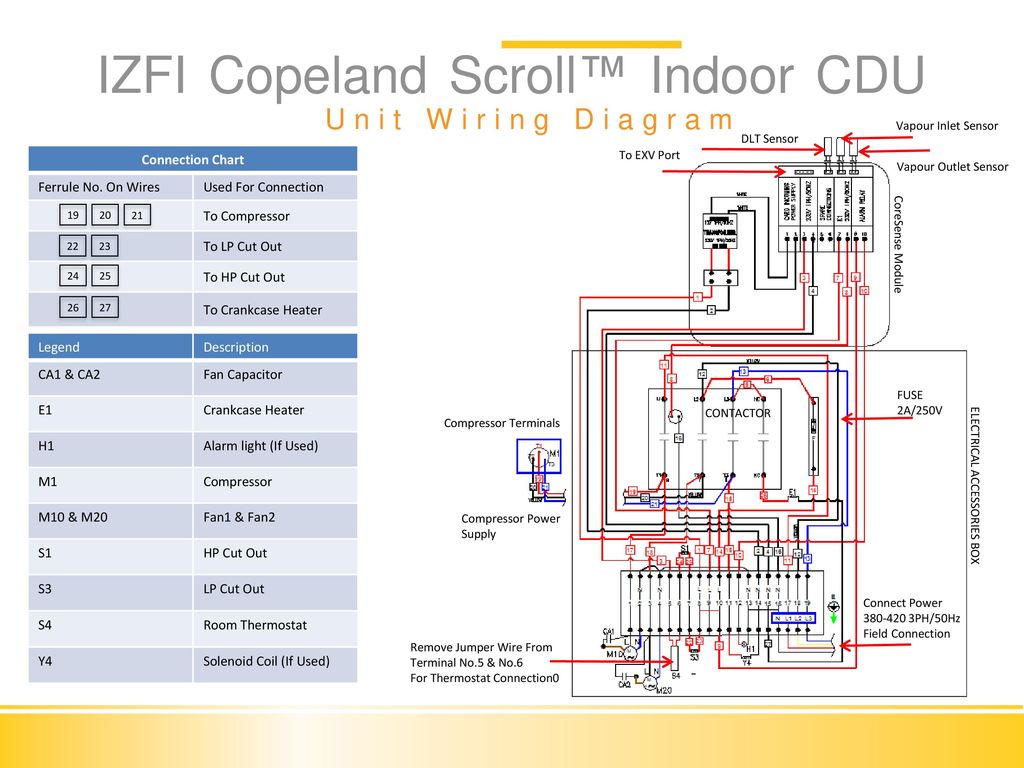
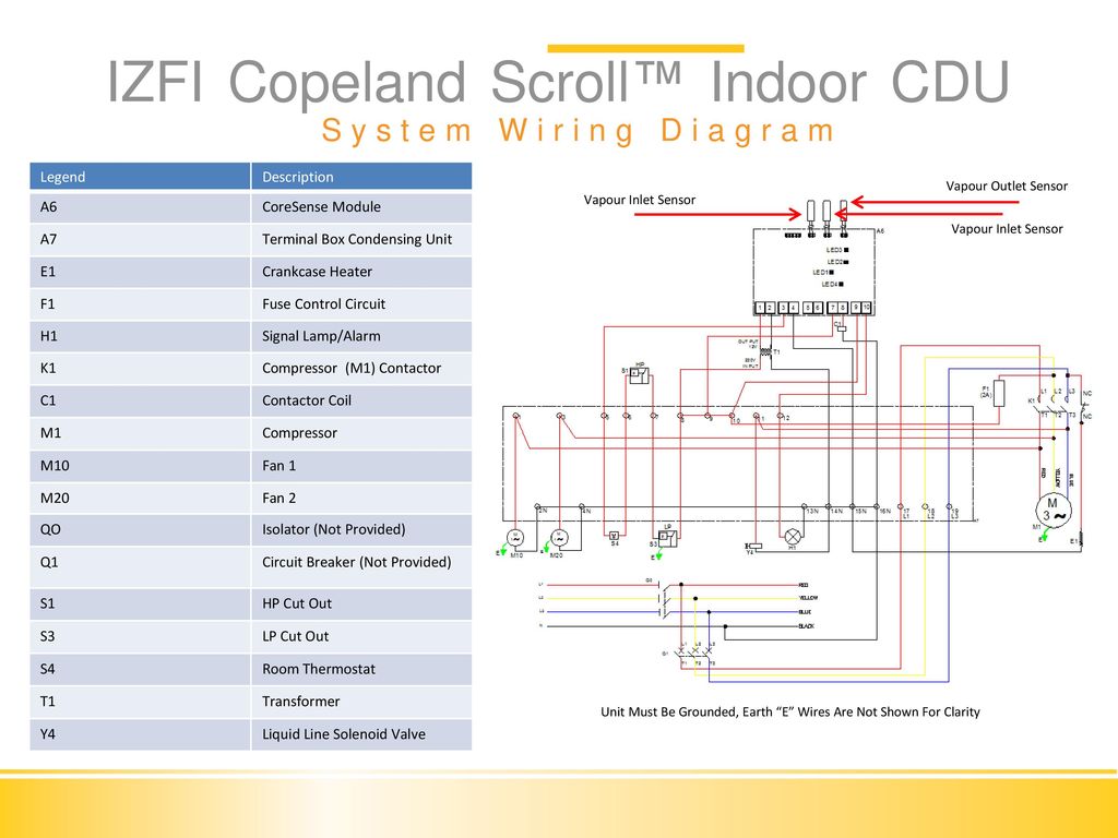
Izfi Condensing Unit Installation Commissioning Ppt Video Online Download
So the crankcase heater ONLY functions when the compressor contactor is OPEN.

Copeland crankcase heater wiring diagram. Route one crankcase heater wire into control box. After surveying commercial air conditioning customers needs and. C PSC motor diagram with start Relay assist kit-that includes a module Potential.
You notice that one side of the heater goes to L1 line side Terminal 1 and the other side is going to L1 load side terminal 2. Single-phase compressors are connected to the Common C Start S and Run R connections. With wiring diagram 1 EWL 500 2830345 Valve plate kit w gaskets 1 510 2490832 Gasket kit 1 520 4577420 Crankcase heater 1 65W 240V External 520 4577431 Crankcase heater 1 65W 120V External 520 4577442 Crankcase heater 1 65W 480V External 520 3210140 Crankcase heater 1 70W 220V Internal For Model E P.
Position heater below compressor terminal box and approximately 2 inches above compressor mounting plate. Wo wiring diagram 1 285 6707718 Gasket. The compressor terminal box has a wiring diagram on the inside of its cover.
22 Typical Braze Connected Tandem wOEL Oil Manifold. The crankcase heater will heat at all times. Terminal box 1 290 2950305 Terminal board assy.
20 Terminal Box Wiring Diagram. Even then it does so by back-feeding through the compressor common and back through the run winding of the. This bulletin describes the operating characteristics design features and application requirements for these compressors.
21 Typical Rotalock Connected Tandem wTPTL Oil Manifold. Wrap heater around compressor base below oil level heater arms may be spread to slip over piping and terminal box. Use this equipment on a grounded system only.
Flexelec the manufacturer of flexible heating cable present the first crankcase heater with integrated thermostat. Wiring Diagram For Copeland Compressor Electrical Schematic Images Diagram 3 Phase Compressor Wiring Internal Full Version Hd Quality Avdiagrams Motoclubgargaros It Diagram 480 Volt Single Phase Wiring Full Version Hd Quality Devdiagram Aitrearchivenezia It. Three-phase compressors are connected to.
Fasten heater firmly in place with clip provided on heater. Use copper conductors only. The 7 to 15 ton ZRKC and ZPKC Copeland Scrollcompressors are designed for a wide variety of light commercial air-conditioning heat pump and chiller applications.
For additional information please refer to the online. 3 phase 1 500 2490774 Valve plate kit w gaskets 1 510 2490785 Gasket kit DK 1 520 2497184 Crankcase heater 1 50W 230V External 520 2728608 Crankcase heater 1 50W 115V External. Crankcase Heaters Models OEM Service Voltage Watts Lead Length 018- 918- in AB AE 0048-02 0048-00 120V 35 30 AB AE 0048-03 0048-01 240V 35 30 AT 0090-00 0049-00 120V 48 30 AT 0090-01 0049-01 240V 48 30.
A crankcase heater designed and patented f. 9-93 052-0822-00 external motor protection-allow time for reset. Place the wiring diagram provided with the kit on the inside of the control box cover.
Crankcase Heater on All Models Rotalock Connections or Stub Tubes Optional Oil Sight Glass Convenient Arrangement of Fittings and Terminal Box Nomenclature Reflects Nominal Capacity Copeland responds to your needs. Wiring diagram 0822 crankcase heater when applied must be connected only to its rated voltage. The crankcase heater should immediately begin to heat.
Circuit Run Capacitor Wiring Diagram A or F opt WDAT2A. Reapply power to the unit. High Locked Rotor Amps.
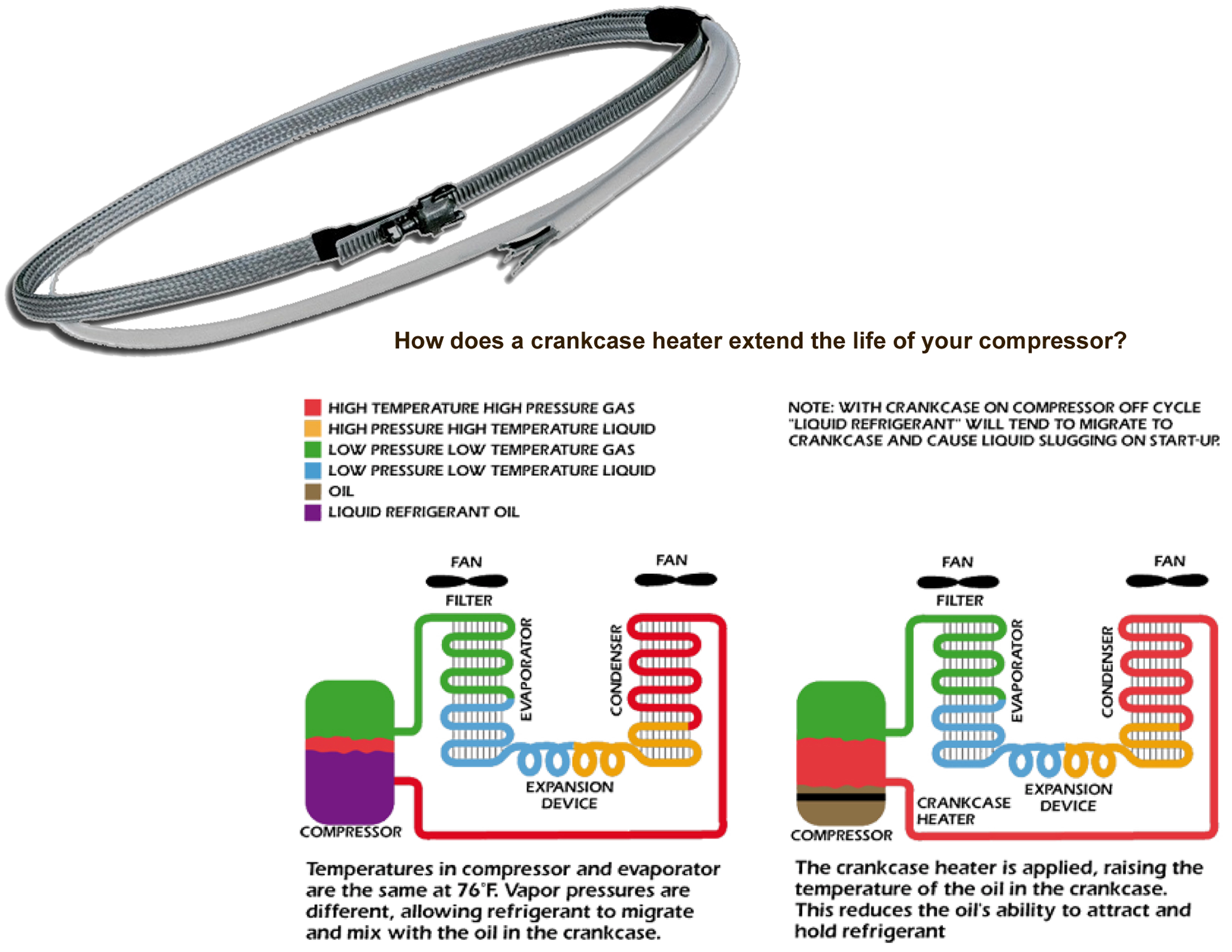
Liquid refrigerant in compres- Add crankcase heater and a sor suction line. They keep the crankcase warm while the compressor is in an off cyclean important step in minimizing refrigerant migration to the compressor. This one covers the wiring of the crankcase heater when used with the single pole contactorThis video is part of the heating and cooling series of training.
S r c motor winding connections line 2 1 rcs 2 1 5 current relay start capacitor. Reinstall the side panel and the unit top and the control box cover. Andweve designed our crankcase heaters with limited wattage to help avoid overheating and carbonizing of the oil.
Before connecting the compressor ensure the supply voltage the phases and the frequency match the nameplate data. 1 phase 1 290 2950327 Terminal board assy. Tecumseh AHE Manual Online.
When most Capacitance crankcase heat systems can be recognized by one or more of the following. Copelands complete line of crankcase heaters offers critical compressor protection. This is a common Carrier heat pump crankcase heater configuration.
Tecumseh to Copeland Brand 9 General Notes 13 Compressor Data Notes Rating Points 14 ZB ZF and ZS Models 15 ZR Models 27 ZFH Models 59 ZP Models 61 ZRTZZ Tandem Models 62 Electrical Diagrams 65 Standard Compressor Drawings 66 Electrical Components 79 Bill of Material Description 82 Accessories 84 Miscellaneous Information Crankcase Heaters 87. Use minimum 75 c wire for ampacity determination.
4 Copeland Semi Hermetic Compressor Product Catalogue Feb 2010 By Andrew Tan Lee Issuu
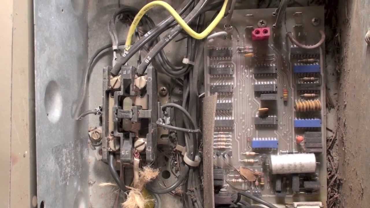
Hvac Compressor Crankcase Heater Wiring Youtube

Blog For Your Health Wiring Diagram Copeland Scroll Compressor
Blog For Your Health Wiring Diagram Copeland Scroll Compressor

The Professor Crankcase Heaters 2014 03 31 Achrnews

Hvac Compressor Crankcase Heater Wiring Youtube
Single Pole And Double Pole Contactors
Crankcase Heater For Copeland Compressors 0263m00006 Click For Models

Hvac Control Wiring Shoeshoneazreen
