42 electrical diagram sensor limit switch location. A1 Drive KM1 Contactor only if a control circuit is needed P1 22 k reference potentiometer.
Atv12h075m2 Wiring Diagram - If you're searching for picture and video information linked to the keyword you have come to pay a visit to the right site. Our site provides you with suggestions for seeing the highest quality video and picture content, hunt and find more enlightening video articles and graphics that match your interests. comprises one of thousands of movie collections from various sources, especially Youtube, so we recommend this video that you view. It is also possible to bring about supporting this site by sharing videos and images that you enjoy on this site on your social networking accounts such as Facebook and Instagram or tell your closest friends share your experiences about the ease of access to downloads and the information you get on this website. This site is for them to stop by this site.
Vsd Inverter Motor 1phase 220vac 1hp 0 75kw Atv12h075m2 Schneider Berkualitas Limited Shopee Indonesia
Single-Phase Power Supply Wiring Diagram A1 Drive KM1 Contactor only if a control circuit is needed P1 22 kΩ reference potentiometer.

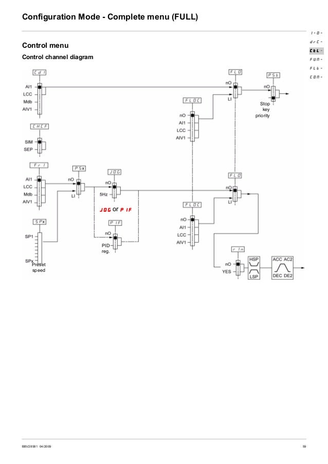
Atv12h075m2 wiring diagram. Application functions b Switching between local control and control via the terminals b Motor control profiles. PA and PC terminals to the braking module DC bus 4. The designer of any wiring diagram must take account of potential control channel failure modes and for certain critical control functions incorporate a way of achieving a safe state during and after a channel failure.
Wire the drive page 20 v Connect the motor ensuring that its connections correspond to the voltage. Enhancements made to version V14 in comparison to V12 New menu. Configure the drive page 32 v Apply input power to the drive but do not give a run command.
Examples of critical control functions are emergency stop and overtravel stop. PA and PC terminals to the braking module DC bus. Serious injury or equipment damage.
Ensure that you follow the recommended grounding connections. 16 BBV28581 042009 Wiring General wiring diagram serious injury. Check that this change is compatible with the wiring diagram.
This can be replaced by a 10 kΩ potentiometer maximum. ATV12H075M2 variable speed drive ATV12 - 075kW - 1hp - 200240V - 1ph - with heat sink Main Range of product Altivar 12 Product or component type Variable speed drive Product destination Asynchronous motors Product specific application Simple machine Assembly style With heat sink Component name ATV12 Quantity per set Set of 1 EMC filter. 27 p06-004840a wiring protecting plate 1.
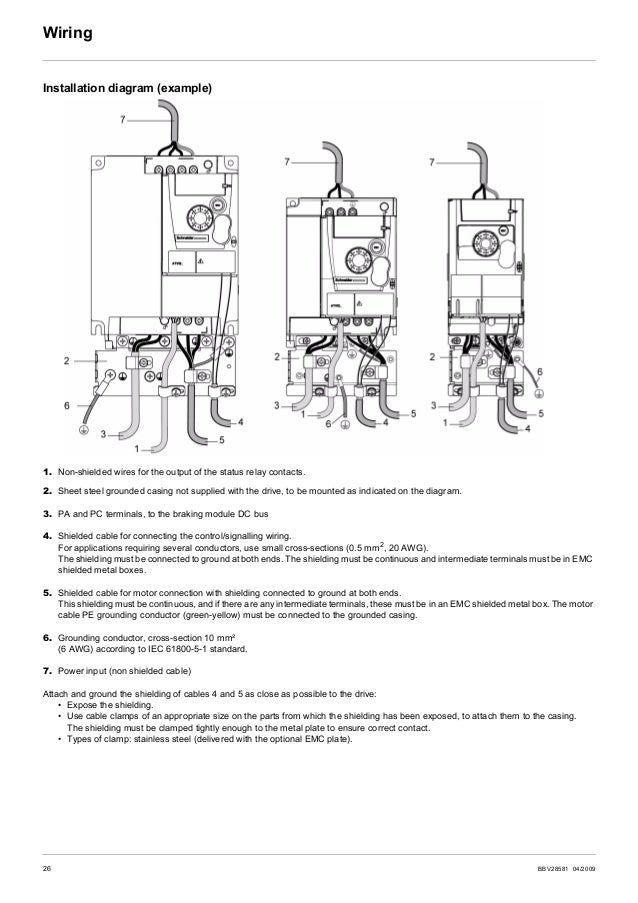
Non-shielded wires for the output of the status relay contacts. Sheet steel grounded casing not supplied with the drive to be mounted as indicated on the diagram. Single-Phase Power Supply Wiring Diagram A1 Drive KM1 Contactor only if a control circuit is needed P1 22 kΩ reference potentiometer.
V Connect the control part. 12500 GBP Main Range of product Altivar 12. Sheet steel grounded casing not supplied with the drive to be mounted as indicated on the diagram.
This can be replaced by a 10 k potentiometer maximum. ATV12H075M2 variable speed drive ATV12 - 075kW - 1hp - 200240V - 1ph - with heat sink Main Range of product Altivar 12. 5 Product data sheet ATV12H075M2 Connections and Schema.
DANGER ATV12H075F1 ATV12H075M2 AND ATV12H075M3 - GROUND CONTINUITY HAZARD An anodized heatsink can create an insulation barrier to the mounting surface. 26 BBV28581 042009 Wiring Installation diagram example 1. ATV12H075M2 variable speed drive ATV12 - 075kW - 1hp - 200240V - 1ph - with heat sink Price.
Altivar 12 variable speed drives For 3-phase motors from 018 to 4 kW Catalog 2010 Courtesy of Steven Engineering Inc-230 Ryan Way South San Francisco CA 94080-6370-Main Office. V Connect the line supply after making sure that the power is off. ATV12H075M2 variable speed drive ATV12 - 075kW - 1hp - 200240V - 1ph - with heat sink Product availability.
Standard VF performance sensorless vector control and pumpfan quadratic profile b Frequency skip b Preset speeds b. ATV11 altivar 12 ATV12H075M2 ATV12H ATV12H037M2 ATV12 ATV12HU15M2 wiring diagram altivar 31 ATV12HU22M2 Text. - External fault EtF-.
ATV12H075M2 with door on front panel open 5 1 Functions The Altivar 12 drive also features the following. Single-Phase Power Supply Wiring Diagram A1 Drive KM1 Contactor only if a control circuit is needed P1 22 kΩ reference potentiometer. 6 Product data sheet Connections and Schema ATV12H075M2 Single-Phase Power Supply Wiring Diagram A1 Drive KM1 Contactor only if a control circuit is needed.
16 BBV28581 042009 Wiring General wiring diagram serious injury. Serious injury or equipment damage. Shielded cable for connecting the controlsignalling wiring.
- Stop type - external fault EPL. Single-Phase Power Supply Wiring Diagram. ATV11 altivar 12 ATV12H075M2 ATV12H ATV12H037M2 ATV12 ATV12HU15M2 wiring diagram altivar 31 ATV12HU22M2 Text.
Inverter atv12h075m2 1hp 220v inverter atv12h075f1 1hp 110v 1 1 3u2 73050215 73050218 carriage inverter. 22 S1A58684 - 042016 Wiring With Single-Phase Power Supply when using GV2P and GV3P manual self-protected combin ation starters for single-phase input appl ications wire. Shielded cable for connecting the controlsignalling wiring.
650 588-9200-Outside Local Area. New wiring labels LO and LO- instead of LO and CLO see pages 18 and 19. Installation diagram example 1.
- External fault assignment EtF. Stock - Normally stocked in distribution facility. For External fault management by logic input.
Non-shielded wires for the output of the status relay contacts. This can be replaced by a 10 kΩ. V Set the motor parameters in Conf mode only.
35 62 tower part list for exp-103. This can be replaced by a 10 kΩ potentiometer maximum.
Ac Drive Altivar 12 User Manual

Cara Setting Inverter Altivar 12 Atv12 Schneider Electric

Cara Setting Inverter Altivar 12 Atv12 Schneider Electric

Schneider Electric Atv12h075m2 Datasheet Electromagnetic Compatibility Electrical Impedance
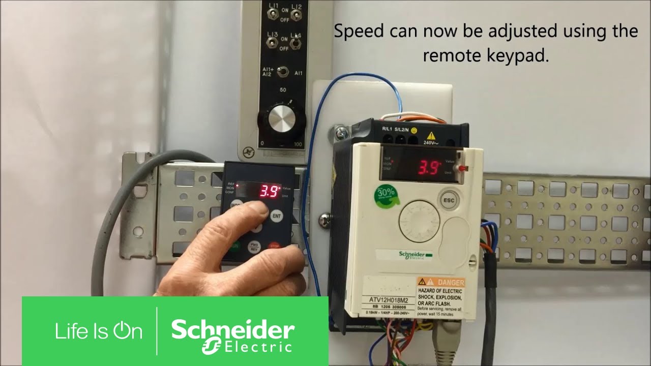
Switching Altivar 12 Speed Control From Terminals To Remote Keypad Schneider Electric Support Youtube

Configuring The Atv12 For Local Mode Operation Schneider Electric Support Youtube
Simor Technology Cara Integrasikan Inverter Altivar Atv12 Ke Iot Blynk
Ac Drive Altivar 12 User Manual

Cara Setting Inverter Altivar 12 Atv12 Schneider Electric
