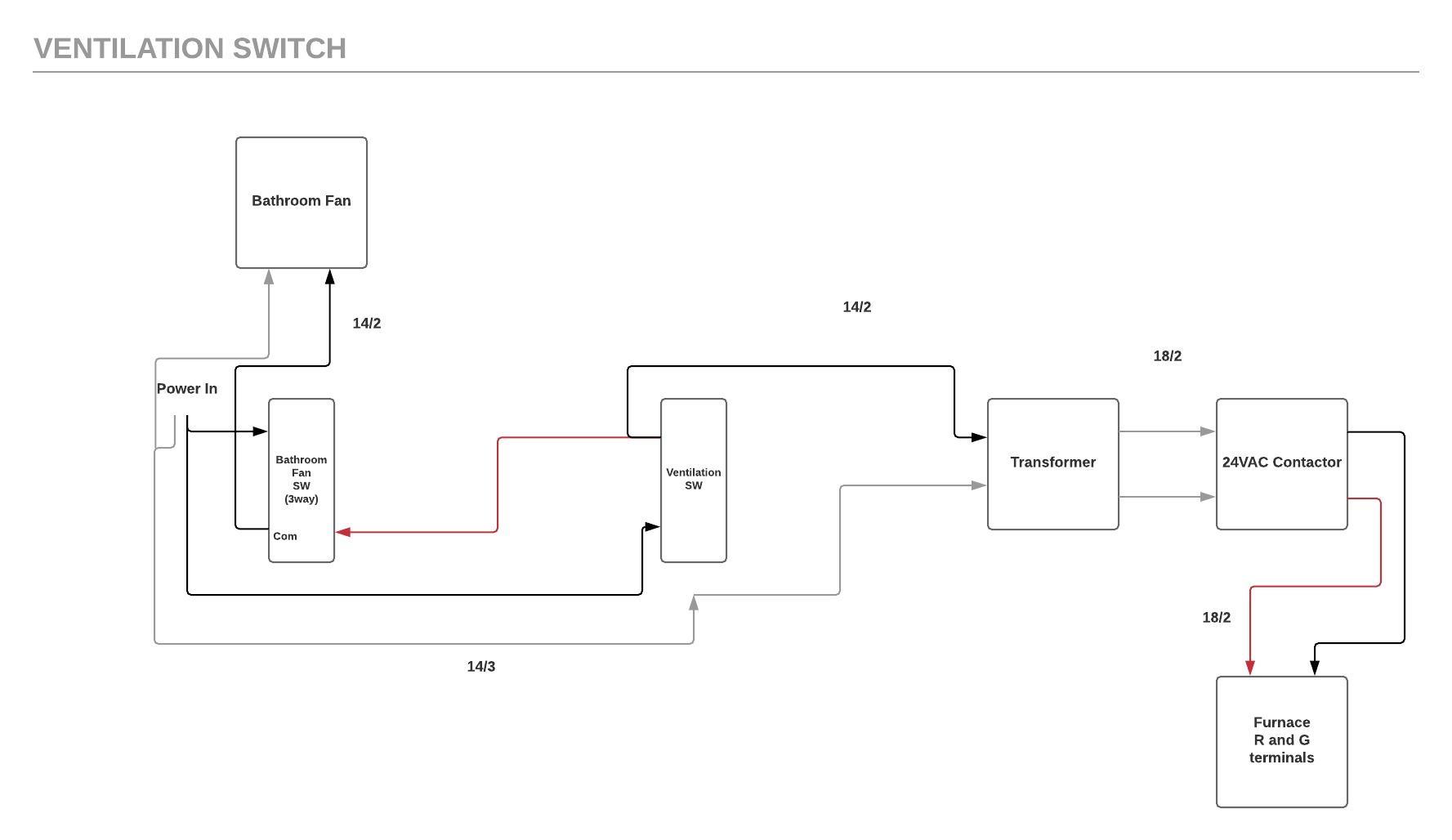
While the ventilation switch is on you cant turn the bathroom fan off by using the regular exhaust fan switch in the bathroom. You need a 3 way switch for the exhaust fan 2 way for the ventilation switch.
Exhaust Fan Interlock Wiring Diagram - If you're searching for video and picture information linked to the keyword you've come to visit the ideal site. Our site provides you with hints for viewing the maximum quality video and picture content, hunt and find more informative video content and graphics that match your interests. includes one of thousands of movie collections from several sources, particularly Youtube, therefore we recommend this movie for you to view. You can also bring about supporting this site by sharing videos and images that you enjoy on this blog on your social networking accounts like Facebook and Instagram or tell your closest friends share your experiences about the ease of access to downloads and the information that you get on this site. This site is for them to stop by this website.

Commercial Exhaust Fan Wiring Diagram
The electrical wiring would be connected with the power source in and load out to the bathroom exhaust fan a neutral wire if required and a ground wire.

Exhaust fan interlock wiring diagram. Inst Maint Wiringqxd 5032008 1002 AM Page 7. Connect this black to the red in the switch box. Please read the complete installation instructions for your specific motion occupancy sensor switch.
The point is to have a manually operable ventilation switch. Motor circuit connection is called interlocking. This is easy to do when the fan starter is in the AUTO position the control system can power the damper actuator and a damper end switch will close the AUTO control circuit.
The green wire from the 183 will go on the G terminal on the furnace and depending what kind of relay you are using will go on either a common terminal or on the other NC contact along with the black wire and then also jumpered to a NO contact. And the switch must be centrally located ABC 932344. Wiring diagrams are shown on pages N-69.
A common problem when combining a building automation system with a 3-phase fan that must open a damper before operating is the damper end switch interlock for the motor starter HAND position. Turning on any piece of cooking equipment under a hood will turn on the exhaust fan for that hood. Simply click the wiring diagram icon to view it Lowers The nameplate of the motor includes a wiring diagram.
Check the power source to see if it is compatible with the requirements of the provided system. As-built wiring diagrams are furnished with each control by the factory and are attached either to the door of the unit or provided within a paperwork pouch internal to the panel. Run a new cable 2 wire from the 3 way switch box to the fan and connect only the black.
Does anyone have any suggestions Thanks. The AFCS wiring diagram list the proper phase voltage and amp load. List of applicable indian standards for electrification work sno.
A simple electrical interlocking control diagram is shown below. 1Ø WIRING DIAGRAMS LN E L1 L2 L3 SC Z2 U2 Z1 U1 Cap. Micro switch 2 for exhaust on in fire should be field wired to terminals NC2 brown C2 red and NO2 black in the control panel from the fire suppression system.
The control center can also be equipped with interlock between the exhaust fans and cooking equipment. 8 common mistakes in reading and creating single line and wiring diagrams. To interconnect the motor circuit.
I have a Belimo 2 position actuator for outside air dampers and I have a small in in line fan and they are going to install an electric heater package. Leave the existing black connected. Refer to the motor manufacturers data on the motor for wiring diagrams on.
Ceiling Fan Wiring Diagram Black White Red and Green Wires P1440 Open wiring supplying the exhaust gas recirculation valve N18 VIK Exhaust Fan Package Wiring diagram of exhaust fan. Appliance wiring material is a classification of underwriters laboratories inc covering insulated wire and cable intended for internal wiring of appliances and equipment. A contact from the control transformer connects to the fan control of your furnace R and G.
PROTECTION Fuses in the circuit should be regarded as protecting the wiring only against short circuit they are not suitable for overload protection. Also two or more exhaust fans may be interlocked together so that they function simultaneously as the principal exhaust fan ABC 932343. Turning off the last pice of cooking equipment under a hood will turn off the exhaust fan for that hood.
The electrical wiring would be connected with the power source in and load out to the bathroom exhaust fan a neutral wire if required and a ground wire. The cabinet is pre-engineered with terminal blocks for most field wiring connections. Its actually pretty useful for getting fresh.
To interconnect the motor circuit in such a way in which the second motor will not start until the first one run likewise the third one motor will not run unless the second one run and so on. Interlock wiring diagram for exhaust fan and cooking equipment. Center provides a common connection point to interlock kitchen exhaust supply and hood lights with the hoods fire suppression system.
Electrical interlocking wiring diagram. Wiring must be in accordance with ASNZS30002007 and local supply regulations. Thermal contacts TB white M 1 Z2 - Yellow Z1 - Blue U2 - Black U1 - Red Bridge L1 and L2 if speed controller SC is not required Anti-Clockwise Clockwise These diagrams are current at the time of publication check the wiring diagram supplied with the motor.
The red wire from the 183 will go on the R terminal on the furnace and the NO contact on the relay. I thought I would some how interlock these devices with the hood exhaust system but Im not sure how to tie this altogether. All AC wiring would be 142 143.
Wiring diagrams are provided with all fans. Connect the power black to one lead of the timer and the black fan wire to the remaining timer lead. Remove the three way switch.
Electrical wiring and connections should be done in accordance with local ordinances and the National. Exhaust Fan Interlock Wiring Diagram. However the fan must have sufficient capacity to provide 50 of the total ventilation requirements of the home ABC 932341.
You turn it on it starts a bathroom exhaust fan at the top of the house and the furnace blower at the same time. Fan Control Centers Accurex. To check out a wiring diagram initially you have to understand just what essential components are consisted of in a wiring diagram and which photographic symbols are made use of to represent them.
The common components in a wiring diagram are ground power supply cord and also connection output devices buttons resistors reasoning gate lights etc. Below is one example of a occupancy motion sensor switch wiring diagram which should be helpful. I was asked to interlock a make up air system in a restaurant.
From there you run 142 to a control transformer. Understand this entire document.
Kitchen Extractor Fan Dimensions Novocom Top
Ventilation Switch Wiring Shd Electric Inc

Exhaust Fan Interlock Wiring Diagram
Hvacquick How To S Wiring 1 Fan Serving 2 Baths With 1 Switch Per Bath With Lights From Hvacquick Com

Diagram Acutator Interlock Wiring Diagram To Fan Full Version Hd Quality To Fan Trudiagram Mbreporter It

Electrical Interlocking Wiring Diagram

The Hall A Wire Chamber Gas System Ops Manual
Diagram Interlock Wiring Diagram Full Version Hd Quality Wiring Diagram Odiagrami Fanofellini It
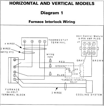
How To Connect Furnace Interlock Relay
